
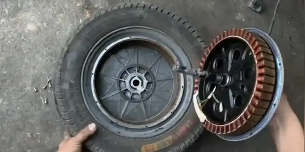
Electric Bicycle Motor Fault Repair Experience: Testing, Diagnosis, and Repair Case Analysis
Electric bicycles use either brushed or brushless motors, and the two types differ significantly in internal structure, controller design, and repair approach. This guide covers motor fault detection and diagnosis in three parts: motor failure analysis, motor testing, and detailed troubleshooting of brushed and brushless motor faults. It then presents twenty-four real repair cases, each presented from fault symptom to repair, covering starting failures, overheating, excessive current, phase loss, abnormal noise, and motor replacement. Because motor testing involves live circuits, rotating parts, and permanent magnets, always follow the safety notes and disassembly precautions in each section before opening a motor or probing a controller.
Fault Detection and Diagnosis Process for Electric Bicycle Motors
Electric bicycles are classified into two main categories based on motor type: brushed motors and brushless motors. The internal structures and controller principles of these two types of motors differ significantly, and their repair approaches are not entirely the same. The controller for a brushed motor consists of a PWM circuit, a high-power field-effect transistor output circuit, and circuits for under-voltage and overcurrent protection, among others.
The indicator system primarily includes battery level display, operating status display, protection circuit display, lighting control, and audible alert circuits. Some models also feature a speed display, with the throttle and brake levers connected to the display panel; these, along with wires for other functions, are routed to the controller via multi-core sheathed cable.
The motor serves as the power source for electric bicycles. Brushed motors are further classified into two types: brushed geared motors and brushed gearless low-speed motors. A brushed geared motor consists of a high-speed motor and a reduction mechanism; it typically uses a flat high-speed motor, with the brushed motor transmitting power to the hub via reduction gears and an overrunning clutch. Brushed gearless low-speed motors consist of a rotor—comprising coils, a commutator, and other components—and a stator—comprising brushes and their holders, rare-earth magnets, and other parts. Brushless motors consist of an outer rotor made of magnets, a stator with three-phase coils, and a position sensor. Since they lack a mechanical commutation system, they feature a simple structure and a low failure rate.
1. Motor Failure Analysis
1.1 Diagnosis and Troubleshooting of a Motor That Will Not Rotate
a. Turn on the power switch and observe the battery level display. If the display is normal, directly measure the controller’s 36V input voltage and 5V output voltage (for brushless motors, this also includes the 10–20V power supply for the position sensor); if the display is abnormal, measure the 36V input voltage.
If the voltage is low, check the fuse, the power switch, the contacts at the battery box output, and the power cable connectors for loose connections; if all the above checks are normal, open the battery box to inspect the battery for swelling or leakage, and verify that the internal wiring is secure. Power supply issues can be resolved by polishing or replacing burnt-out contacts, cleaning and tightening the power cables, replacing the power switch, or replacing the battery.
b. Once the 36V input is confirmed to be normal, check the controller’s 5V output (the power supply for the brushless motor sensor should be approximately 10–20V). If the 5V output is abnormal, disconnect the throttle; if the issue persists, the controller is faulty. If the 5V output is normal and the voltage at the output terminal ranges from 1 to 4.2V when the throttle is turned, the throttle is functioning properly; otherwise, the throttle is faulty and should be replaced.
c. Use a multimeter to check the output voltage. If the throttle is functioning properly but the motor still does not turn, check the brake lever next. Brake levers come in two types: mechanical and electronic. For mechanical brake levers, measure the resistance between the two leads; in both the normal and braking states, the resistance should vary between ∞ and 0. If not, the brake lever is faulty.
d. For electronic brake levers, first check the operating power supply (approximately 5–15 V). If normal, measure the voltage at the signal output terminal between the normal state and the braking state; it should switch between 0 V and 5 V (or 15 V), otherwise the electronic brake lever is faulty. If the 5V (15V) power supply is abnormal, it indicates a controller malfunction. A faulty brake lever remains in the braked state, causing the controller to have no output; consequently, the motor does not rotate. Replace the brake lever or disconnect its connector to release the brake. If the motor rotates normally, the issue is resolved; otherwise, the controller is faulty.
e. Brushed motor troubleshooting. Disconnect the motor from the controller, then measure the resistance between the two motor leads. When the motor is functioning normally, the resistance is very low; if you slowly rotate the motor, the resistance remains stable and does not fluctuate. Otherwise, the motor is faulty. Common faults include broken motor wires, worn brushes, and arcing or oxidation of the commutator. Replace the motor wires and brushes; grind the commutator; and clean the insulation between the commutator segments, ensuring it is recessed below the commutator segments by a certain depth.
For brushed geared motors, if you hear the motor running when power is applied but the hub does not rotate, it indicates wear on the reduction gears. Open the hub and replace the damaged gears.
f. Brushless motor troubleshooting. First, check the sensors. Turn on the power switch and measure the supply voltage between the red (+) and black (-) wires of the five sensor leads coming from the controller; it should be 5V (or 10V, 15V, depending on the controller). Otherwise, the controller is faulty. If the sensor power supply is normal, rotate the brushless motor and measure the three sensor output terminals; each should exhibit a regular fluctuation between 0V and the sensor supply voltage. Otherwise, the sensor is faulty.
g. The brushless motor sensor consists of three switching Hall elements, which detect the position of the rotor magnets, which, through the controller’s electronic switches, cause current to flow periodically through the stator coils, thereby driving the motor’s rotation.
Check the three motor power wires for damage. Brushless motors produce high torque; if anti-rotation measures are inadequate, the shaft may rotate, causing the motor leads to be severed. If the motor leads are long enough, remove the damaged section and reconnect the leads from inside the motor; otherwise, replace the leads. Fabricate a new anti-rotation plate to lock the shaft in place within the frame or mount, preventing it from rotating under the motor’s torque.
h. Brushed controllers are based on PWM (Pulse Width Modulation) circuits, with the TL494 being a commonly used core component. It controls pulse width modulation via the throttle and associated circuits, and ultimately uses field-effect transistors to adjust the on-off ratio of the power supply across the motor terminals, thereby achieving motor speed control.
Commonly used field-effect transistors include the IRFZ44N, IRFZ48N, IRF2807, and IRF3710. These devices use the TO220 package, which is compact and capable of handling high currents, making them an ideal choice.
i. Common controller faults include field-effect transistor breakdown or burnout, damage to the freewheeling diode, power supply failure, and protection circuit failure.
After performing the above checks and ruling out faults in the power supply, throttle, and motor, it can be determined that the controller is faulty.
j. When replacing the controller, ensure that the controller is compatible with the output type of the throttle and brake levers: whether it is a forward-control throttle with a range of 1–4.2V or a 4.2–1V reverse-control throttle; whether the brake lever is an electronic or mechanical switch; if mechanical, whether it is normally open or normally closed; and if electronic, whether it operates on a high or low logic level. Failure to do so may result in new malfunctions after replacement. The throttle and brake levers must be rematched according to the new controller.
1.2 Motor Runs Continuously
If the motor runs continuously and is not controlled by the throttle, this is a typical controller malfunction, most commonly seen in brushed motors. The primary cause is a field-effect transistor (FET) breakdown, where the 36V power supply is applied directly to the motor through the broken transistor.
Another reason for continuous motor operation is a faulty throttle, causing the controller to remain in a high-speed rotation state.
If this occurs with a brushless motor, it is due to a throttle malfunction that keeps the controller in a constantly “on” state; replacing the throttle will resolve the issue.
1.3 Power Does Not Turn On; Fuse Blows
This is caused by a short circuit in the vehicle; common causes include contact between headlight wires or a shorted controller. The fault location can be identified using the resistance testing method. Repair the insulation on the wires and replace the controller to resolve the issue.
1.4 The motor runs intermittently and vibrates while riding
Common causes include: ① The battery has reached the end of its service life (high internal resistance); ② Poor contact in the power cable; ③ Worn motor brushes or oxidized commutator causing poor contact.
Turn on the power while riding and observe the battery level display. If the battery level is low, it is a power supply issue; if the battery level is normal, it is a motor issue.
Disassemble the faulty motor and inspect the brushes and commutator. Replace worn brushes, polish the oxidized commutator with an oilstone, and clean the insulation grooves between the commutator segments so they are flush with the commutator segments.
Check the contacts, power cord connectors, and power switch for poor contact, which can cause high contact resistance and a large voltage drop during operation, resulting in the motor starting and stopping intermittently.
The battery has reached the end of its service life and has high internal resistance, resulting in a normal no-load voltage but a drop in terminal voltage under load. This triggers the controller’s undervoltage protection; replacing the battery will resolve the issue.
1.5 Very high idle speed, but lacks power while riding
Check the motor current during idle operation; under normal conditions, the no-load current is around 0.5 A. If the current is too high, it indicates a motor malfunction; if the current does not rise when a load is applied, it indicates a controller malfunction. Check according to the methods described above.
1.6 Controller Burnout
Motor malfunctions fall into two major categories: mechanical and electrical. Mechanical malfunctions are relatively easy to detect and repair, while electrical malfunctions require voltage or current testing for diagnosis.
2. Motor Testing
2.1 General Motor Testing
Testing of electric bicycle DC motors primarily focuses on performance. If issues are identified during testing, further inspection should be conducted on the windings, commutator, bearings, as well as the rotor, armature runout, and air gap.
General testing of electric bicycle motors primarily covers the following aspects:
a. Check whether the power supply connections are correct.
b. Check whether the commutator is eccentric and whether the contact area between the brushes and the commutator is normal. Under normal conditions, the commutator should cover at least 75% of the brush cross-sectional area; otherwise, poor contact may cause sparking.
c. Check whether the spring tension of the brushes is appropriate and whether the brushes are correctly assembled in the brush holders. Insufficient spring tension or incorrect positioning will both cause sparking at the brushes.
d. Check whether the insulation resistance of the windings meets specifications. The insulation resistance of a motor is generally tested at cold (room temperature) conditions and then converted to hot (75°C) conditions; if it meets the requirements, it is considered acceptable. Normal insulation resistance at hot conditions should be less than 5 MΩ.
2.2 Quick Test for Motor Condition
The quick test methods for determining motor condition are as follows:
a. While the motor is idling, listen for any abnormal noises.
b. With the power off and the motor leads disconnected, check whether the motor rotates smoothly.
c. Disconnect the leads of a brushed motor and use a multimeter set to the resistance range to check for continuity.
d. With the brushless motor unpowered, manually rotate the motor to check for excessive resistance (this should be done while any two motor wires are connected).
e. For a brushless motor, use a multimeter to check whether the resistance values of the three Hall effect sensors are normal.
f. For a brushless motor, use a multimeter to check whether the three motor wires are shorted or open.
g. For a brushless motor, use a multimeter to check whether the resistance values of the Hall effect sensors change with the rotation of the motor.
3. Diagnosis and Troubleshooting of Motor Faults
3.1 Brushed Motor Faults
Common faults in brushed motors include: failure to start, abnormal operation, excessive speed, excessive slowness, unusual noises, and sparking. Common failure points include the brushes, commutator, windings, brush holders, springs, gear reduction systems in gear-driven configurations, as well as demagnetized permanent magnets and bearings.
3.1.1 Failure to Start The primary cause of a brushed motor failing to start is an open circuit. This includes open circuits in the windings, open circuits between the windings and the commutator, detached brush leads, spring failure, and wear on the brushes or commutator. Specific troubleshooting methods are as follows:
a. Open circuit in the windings. Use a multimeter to test two copper segments opposite each other on the commutator. If the resistance differs from that of other areas, it indicates a fault in the commutator segment. Hold one probe stationary while moving the other left and right. If the meter reading changes, it indicates that the coil connected to that copper segment is open; if the resistance remains high regardless of movement, it indicates that the commutator segment contacted by the other probe is open.
b. Solder joint failure between the coil and the commutator copper segments. The symptoms are identical to those of a coil open circuit during operation. During inspection, use a bamboo needle to gently prod the solder joints where the coil ends meet the copper segments; if there are signs of movement or immediate separation at the unsoldered or cold solder joints, simply resolder them. If the coil is open and the break is inside the winding, it is difficult to repair. If there are only one or two breaks, a short-circuit connection can be made at the commutator segment; if there are many breaks, the entire winding must be replaced.
c. A few coils are open. Sometimes, one or two open-circuit coils do not affect operation; they merely cause a decrease in speed and torque, as well as unstable performance. As the number of open-circuit coils increases, the motor will be unable to start.
3.1.2 Commutator Issues Abnormal noises are related to excessively stiff springs, worn brushes, bulging insulation shims between commutator segments, and protrusions on the armature. Inspect and replace any damaged components to resolve the fault.
3.1.3 Short Circuits The main causes of short circuits in motors are: ① a short circuit in the windings; ② a short circuit between the copper segments of the commutator.
The difference between a winding short circuit and a short circuit between commutator segments is that a winding short circuit manifests as high current and significant sparking during operation.
There are two methods for locating short circuit points:
a. Short circuits in the winding circuit. There are two methods for locating short circuits in the winding circuit:
① For windings with few turns and low resistance, use a multimeter to measure the resistance of the commutator. Connect the motor to a 6V AC power source to generate an induced electromotive force, then use the multimeter probes to measure the voltage between two adjacent commutator segments, moving gradually in one direction. When the voltage between two adjacent commutator segments drops abnormally low (unlike the others), this indicates that the coil connected to the multimeter probes is the short-circuit point.
② For windings made of fine wire with a high number of turns and high resistance, a multimeter can be used for testing. The testing method is as follows:
a. For wave-wound windings, there is no need to disassemble the motor. Connect the multimeter probes to the brush leads and slowly rotate the armature. Under normal conditions, the measured resistance values should be consistent. If an anomaly is detected at a certain point, it indicates that the two commutator segments contacted by the brush are the short (open) circuit point.
b. When the winding is layered, the pitch is generally 1. Use a multimeter to measure the resistance between two adjacent commutator segments; any abnormality indicates a short (open) circuit point.
b. Commutator segment short circuit. Short-circuit points on the outer periphery of the winding are easy to repair; if located inside the winding, the coil should be rewound or the armature replaced, depending on the situation.
Short circuits in commutator segments are primarily caused by the accumulation of worn-down carbon dust and copper filings in the insulating slots between the segments. Through repeated operation, these particles are compressed into a dense, conductive mass, causing adjacent commutator segments to short-circuit. Use a brush to thoroughly clean the carbon dust from the surface around the commutator, use a scraper or hacksaw blade with a width matching the gap between commutator segments to carefully scrape away the accumulated carbon deposits in the slots, cleaning with a brush as you go. After scraping the short-circuited areas, perform testing until all short circuits are resolved.
Note: The commutator segments are connected to the windings, and accurate results cannot be obtained with a multimeter unless the coil at that point is disconnected. Whether conducting a preliminary test or a test after repair, the test must be performed with the coil disconnected. After completion, the original commutator segment at the disconnection point must be rewelded to restore the unit to its original condition.
(4) Commutator Segment Grounding: The commutator segments are insulated from the shaft, and the winding coils are also insulated from the armature core. If an abnormality occurs resulting in a ground fault, the motor will not operate normally.
To troubleshoot, secure one probe of the multimeter to the shaft (or the housing in the case of a hub motor); use the other probe to test each commutator segment in turn—the one with the lowest resistance indicates the short-circuit point.
(5) Brush Wear: If the motor’s brushes are sometimes too soft or if hard foreign objects enter, this can cause wear on both the brushes and the commutator segments. Wear results in sparking, wasted electrical energy, reduced power output, and sometimes even unstable operation.
When brush wear reaches half of the original design length or the contact area is less than 75% of the total area, the brushes should be repaired or replaced. When replacing them, pay attention not only to the brush dimensions but also to selecting the correct hardness; otherwise, the commutator segments will wear out quickly, and replacing commutator segments is a relatively cumbersome process. Brushes should be pre-ground before replacement to ensure a better fit with the commutator segments, thereby reducing power consumption and commutator segment wear.
(6) Commutator Segment Wear Motor commutators come in two forms: disc-shaped, arranged in a plane, and cylindrical, arranged around the shaft. Different configurations require different repair methods.
The consequences of commutator segment wear are the same as those of brush wear, but repairing commutator segments is more difficult than running in brushes. For minor wear, sand the segments flat and smooth using fine sandpaper. Whether the commutator is cylindrical or planar, the running-in process must be performed properly and meet the requirements of being flat, smooth, and circular. In cases of severe wear, the armature should be replaced with a new one.
According to specifications, the insulation layer between commutator segments should be 0.5–1 mm lower than the commutator segments themselves; if this is not the case, it must be adjusted. The adjustment method involves using a scraper or a hacksaw blade to cut along the direction of the insulation groove until the mica insulation is 0.5–1 mm lower than the commutator segments.
3.2 Brushless Motor Failures
In brushless motors, the permanent magnets, windings, Hall effect sensors, and bearings are prone to failure. Brushless motors do not experience commutator failures; apart from Hall effect sensors, other failures are essentially the same as those in brushed motors.
3.2.1 Motor Responds When Powered On but Does Not Rotate The simplest way to determine if a brushless motor is faulty is to short-circuit the three power wires together, and then turning the motor by hand. If it is very difficult to turn or does not turn at all, the motor is in good condition; if it turns or turns easily after the three wires are short-circuited, the fault lies in the windings, and further testing and inspection are required.
3.2.2 Hall Sensor Failures Hall sensors, also known as position sensors, are primarily prone to the following failures: sensor detachment, broken leads, and Hall IC failure.
a. The sensor is generally mounted on the end of the armature with lead wires, near the permanent magnet. If it has come loose, use resin to securely reattach the Hall IC to its original position.
b. If the lead wires are broken, re-solder them. If the break occurs at the point where the lead wire meets the IC, replacement is necessary.
c. Hall IC failure. First, determine whether the fault lies within the circuit itself or with the power supply; this can be determined by measuring the voltages at the pins. The specific measurement method is as follows:
The sensor typically has three pins: one is the positive power supply terminal, another is ground, and the third is the status output pin. Once the positive and ground pins are identified, the remaining pin is the output pin. Turn on the controller power to activate the sensor. Find a magnet with a high magnetic field strength and repeatedly bring its N and S poles close to the sensor. Use a milliammeter or signal tester to measure the changes in the signal between the output pin and ground. The signal is simple, consisting of only two states: “present” and “absent,” or 1 and 0. When the S pole is present, a signal of 1 (+) is detected. For latch-type Hall sensors, this fixed signal state is maintained until the N pole is brought near, at which point the signal changes to 0 (–); this is normal behavior.
If no signal is detected when either the S pole or the N pole is brought near the sensor, the Hall IC is determined to be faulty and should be replaced with a new one. A signal indicates a high logic level with a voltage output of 5–6 V or higher. No signal indicates a low logic level with no voltage output.
Another possibility is a lack of power. Check that there is a voltage of at least 4.5 V between the power supply and ground; otherwise, the power supply is faulty.
Note: When replacing the sensor, ensure it matches the original sensor in type and model, and that the orientation (front and back) is the same to prevent incorrect pin sequencing.
The Hall IC is a small rectangular chip with a notched corner; simply identify the direction of the notch before desoldering. Furthermore, its three leads are different colors; make a note of the color sequence beforehand to avoid errors during soldering.
3.2.3 Magnet Detachment Magnets must not be dropped or subjected to impacts to prevent accidental demagnetization; nor should they be left exposed for extended periods. The armature should be returned to the housing as soon as possible to form a closed circuit around the magnet; otherwise, demagnetization may occur.
After a magnet falls out, a metallic grinding sound will occur with each full rotation of the wheel. While this has little impact on operation—it merely slows down the speed and increases power consumption—it should be repaired promptly. The repair procedure is as follows:
The N and S poles of the magnets inside the external rotor are arranged alternately (in the form of curved thin strips). There is no need to distinguish between “front” and “back”; simply align them according to the original markings. When adhering the magnets, ensure they are flush and aligned with the others, without protruding or becoming misaligned, to guarantee that the motor’s air gap and mechanical dimensions remain unaffected.
It is best to temporarily install the armature into the housing before the magnets are fully cured.
Some motor faults are closely related to the controller; when analyzing faults, one should not limit the investigation to the motor itself but also consider power supply issues, wiring problems, and other factors. For example, the Hall effect sensors or magnets in the speed control knob may become dislodged, or the Hall effect sensor wiring may be broken.
3.2.4 Speed Control Grip Faults The primary reasons why a motor fails to rotate are: the magnets or Hall effect sensors inside the speed control grip have come loose, or the Hall effect sensor wiring has been disconnected. These types of faults occur more frequently than internal motor faults, and they often present no tactile feedback or unusual sounds. When the motor exhibits abnormal control behavior, a speed control grip fault should be considered. Although this is not classified as a motor fault, it is often associated with motor troubleshooting. The specific troubleshooting steps are as follows:
a. First, disconnect the connector between the speed control grip and the controller.
b. Loosen the speed control grip’s mounting screw and slide the grip off the handlebar.
c. Unscrew the screw on the throttle grip itself to remove the grip sleeve. When removing it, remember the positions of the internal components, especially the reset spring.
d. Check whether the magnet and Hall effect sensor have come loose or shifted out of place.
e. If they have come loose, secure them firmly with resin. If everything is in place, reassemble the unit as is.
f. Wire breaks are very common; simply reconnect the broken wire. However, ensure the wire length does not interfere with the connection to the controller.
If the wire is broken at the base of the Hall sensor, you must replace it with a Hall sensor of the same model. Before bonding the new sensor in place, ensure the notch is aligned with the original orientation, and solder the three leads onto the connector in their original sequence.
Case Studies in Electric Bicycle Motor Repair
Case 01: Motor Does Not Rotate or Runs Continuously
Fault Symptoms:
The motor does not rotate, or it runs continuously.
Troubleshooting:
Faults where an electric bicycle motor does not rotate or runs continuously can be troubleshot following the procedure shown in Figure 1.
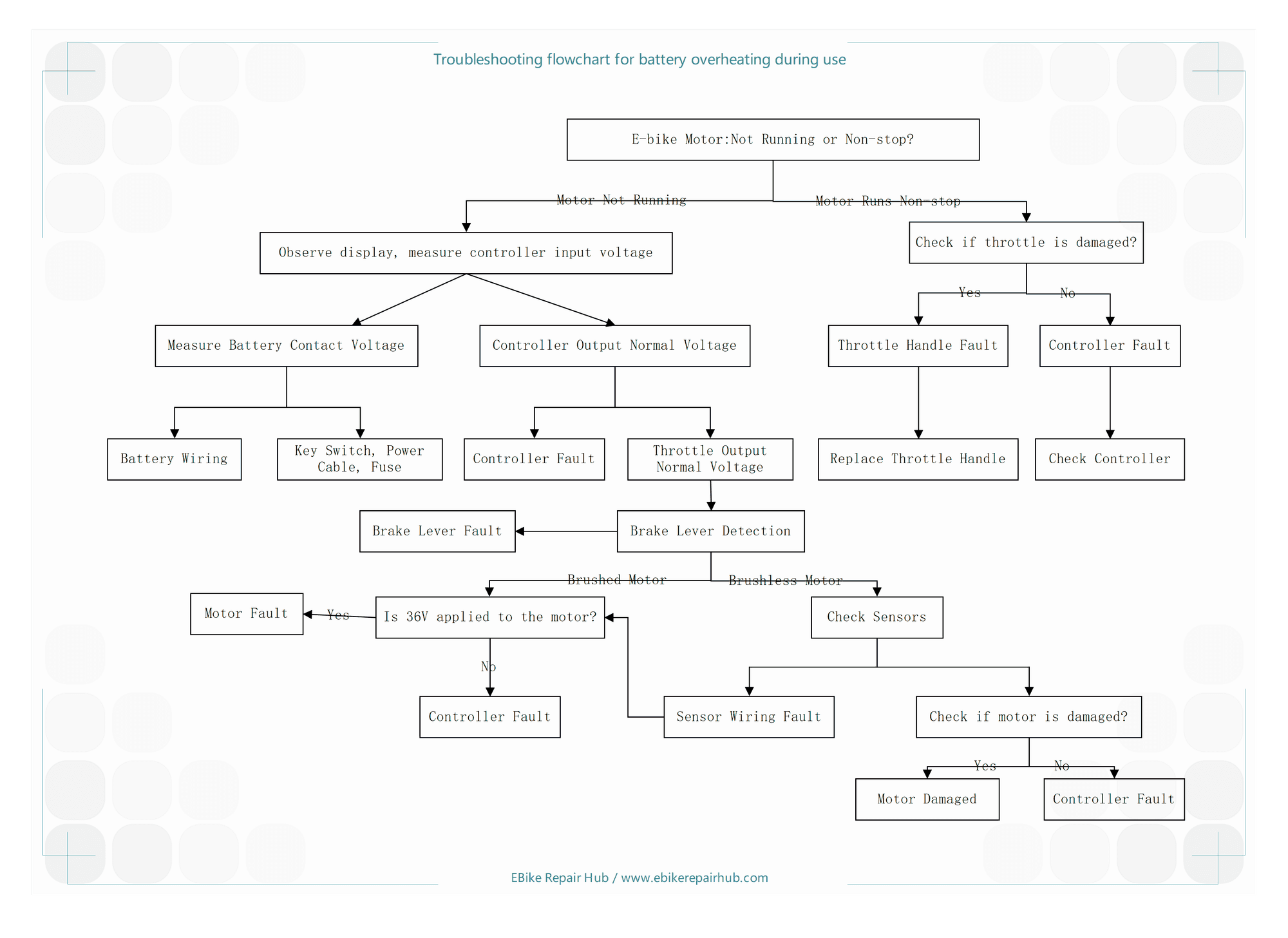
Figure 1: Troubleshooting Process for Electric Bicycle Motors That Do Not Spin or Spin Continuously
For the complete troubleshooting procedure, see: E-Bike Motor: No Rotation & Runaway Diagnosis
Case 02: Brushless Motor Does Not Spin
Fault Symptoms:
The brushless motor does not spin.
Troubleshooting:
The control principle of a brushless motor is shown in Figure 2.
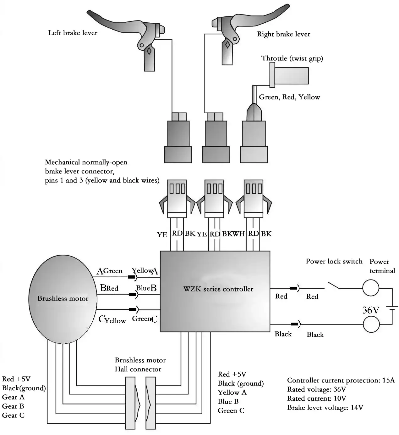
Figure 2: Brushless Motor Control Schematic
If a brushless motor fails to rotate, the troubleshooting procedure is shown in Figure 3.
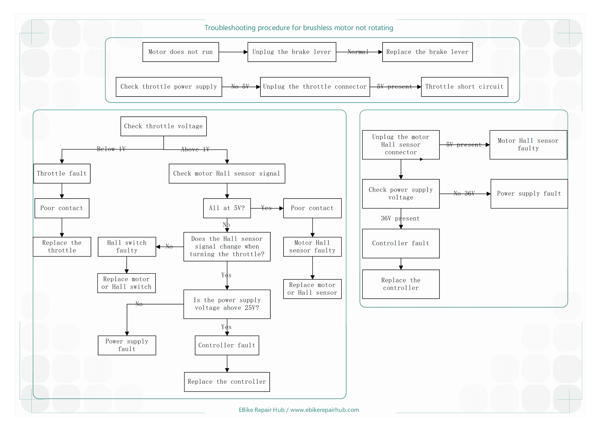
Figure 3: Troubleshooting Procedure for a Non-Rotating Brushless Motor
For the complete troubleshooting procedure, see: E-Bike Brushless Motor No Rotation: Hall Sensor Supply Test
The brushless motor sensor consists of three switching Hall elements, which are used to detect the position of the rotor magnets. Through the controller’s electronic switches, current is passed through the stator coils in a regular pattern to drive the motor’s rotation.
During troubleshooting, first turn on the power switch and check the voltage between the red (+) and black (-) wires of the five wires leading from the controller to the sensor; this voltage should be 5V, 10V, or 15V (the voltage varies depending on the controller model). If the voltage is abnormal, it indicates a controller malfunction.
If the sensor power supply is normal, rotate the motor to check the output voltage at the three sensor wires; it should fluctuate regularly between 0V and the sensor power supply voltage (5V, 10V, or 15V). If this fluctuation is not observed, the sensor is faulty.
After confirming that all the above checks are normal, finally check whether the motor’s three power supply wires have good contact. If the leads are damaged, reconnect the leads from inside the motor or replace them to resolve the issue.
Case 03: Brushed Motor Fails to Start (Part 1)
Fault Symptoms:
The brushed motor fails to start.
Troubleshooting:
This electric bicycle uses a 36V hub motor and a ZKC3615 brushed hub motor controller; its circuit diagram is shown in Figure 4.
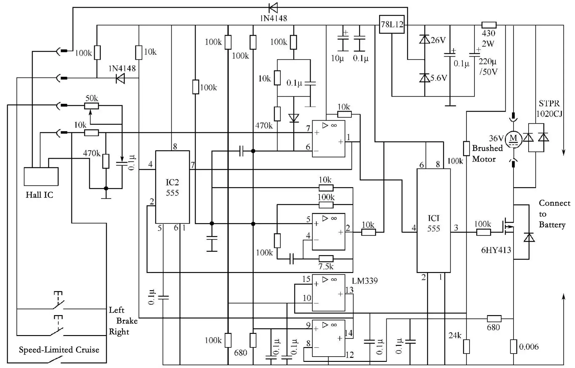
Figure 4: Circuit Diagram of the ZKC3615 Brushed Hub Motor Controller
The troubleshooting procedure for a motor that fails to start is as follows:
First, check whether the speed control throttle and output wires are functioning properly. If they are, check whether the controller or motor connectors have come loose; if they have not come loose, check whether the left and right brake levers have cut off power. After confirming everything is normal, unplug the speed control connector, turn on the power switch, and check whether the connector has a 5V voltage; if there is no voltage, this indicates a problem with the power supply section inside the controller; If the voltage and the controller’s power supply section are both normal, this indicates a fault inside the controller or the motor, and further troubleshooting is required.
Typically, the absence of a 5V speed control voltage—which prevents the motor from starting—is caused by an open circuit in the voltage regulator diode within the speed control power supply section. Replacing the damaged component(s) will resolve the issue.
Case 04: Brushed Motor Fails to Start (Part 2)
Fault Symptoms:
The brushed motor fails to start.
Troubleshooting:
Common causes of a brushed motor failing to start include: an open circuit in the armature circuit, incorrect connection of the starting resistor, high load counter-torque, inter-turn short circuit in the armature windings, short circuit between commutator segments, poor brush contact, insufficient brush pressure, misaligned brushes, detached rotor solder joints, excessive motor load, etc.
Troubleshooting methods are as follows:
a. Locate the short circuit or ground fault, then perform a local repair or replacement.
b. Reconnect the starting resistor.
c. Locate the open circuit or short circuit, then perform a local repair or replace the winding.
d. Locate the short circuit between commutator segments, and perform a local repair or replace the commutator segment.
e. Re-grind the brush springs to restore proper pressure.
f. Adjust the brush position.
g. Locate the detached welds and re-solder them.
Case 05: Motor Does Not Run After Power Is Applied
Fault Symptoms:
The motor does not run after power is applied.
Troubleshooting:
The main causes of this fault are: ① Loose battery connections; ② Disconnected controller power cable; ③ Loose or damaged motor plug; ④ Malfunctioning speed control throttle or brake cut-off switch, etc.
a. First, check the dashboard indicator light. If the indicator light is off, use a 50V multimeter to check whether the battery’s output voltage is normal. If the voltage reading is abnormal, check the battery inside the power box; in most cases, the controller is faulty. If the voltage is normal, check whether the wires connecting the power switch are broken or have poor contact, and whether the switch itself is damaged.
If the dashboard indicator light is on, check the connection wires between the battery and the hub directly, then test the controller.
b. Check whether the 10A fuse on the outside of the (brushed) controller has blown. If it has blown, simply replace the fuse.
c. If the motor still does not operate, check the speed control throttle and the power-off brake lever. If the 5V power supply is normal and turning the throttle produces a voltage output of 1–4.5V, the throttle is functioning properly; otherwise, replace the throttle.
d. If the throttle power supply is normal but the motor does not turn, check the brake lever. There are two types: mechanical and electronic. For mechanical brake levers, measure the resistance between the two leads; in both normal and braking states, the resistance should vary between 0 and ∞. Otherwise, the brake lever is faulty.
For electronic brake levers, first check whether the operating power supply (5–15 V) is normal. If normal, measure the voltage at the signal output terminal during normal operation and braking; it should generally vary between 0 and 5 V or 0 and 15 V; otherwise, the brake lever is damaged.
If a brushed hub experiences faults such as an open circuit in the motor connection wires or damage to the brushes and commutator segments, the hub will not rotate; for brushless hubs, use an electric bicycle tester to inspect the three Hall effect sensors. If any are damaged, they should be replaced.
Case 06: Motor Overheating
Fault Symptoms:
The motor overheats during operation.
Troubleshooting:
Motor overheating occurs when the temperature of the motor’s end cap exceeds the ambient temperature by more than 25°C during operation, indicating that the motor’s temperature rise has exceeded the normal range. Generally, the temperature rise of a motor should be below 20°C.
Common causes of motor overheating include: ① power supply voltage that is too high or too low; ② inter-turn short circuit in the armature windings; ③ air gap eccentricity; ④ Short circuit in the core; ⑤ Friction between the stator and rotor cores. The most direct cause is excessive motor current.
An increase in current indicates a decrease in resistance or induced emf. A decrease in resistance is generally caused by a short circuit or open circuit in the windings, while a decrease in induced emf is caused by demagnetization of the permanent magnets or short circuits and open circuits in the windings.
Troubleshooting methods include: Adjust the supply voltage to the standard value; identify the cause of excessive or insufficient magnetic current and take appropriate corrective action; locate the short-circuit point and perform localized repairs or replace the windings; perform localized repairs or replace the core; align the shaft and replace the bearings, etc.
If the fault persists after the above inspections and repairs, the motor must be replaced.
Case 07: Excessive Motor Current
Fault Symptoms:
The motor current is excessive.
Troubleshooting:
Excessive current within the motor will cause the motor to overheat. See Table 1 for the causes and troubleshooting methods.
Table 1: Causes and Troubleshooting Methods for Excessive Motor Current
| Cause of Failure | Fault and Troubleshooting Method | Cause of Fault | Fault and Troubleshooting |
| Short circuit between the positive and negative terminals of the battery | Eliminate the short circuit | Short circuit in the commutator segments | Clean and polish the commutator segments |
| Misalignment of the positioning magnets | Re-adhere | Excessive tightness between the shaft and bearings | Grind the shaft |
| Uneven gaps between the brushes | Adjust the brush gaps | When an electric bicycle fails to start from a standstill, reduce the load | Assist with pedal power |
| Inter-turn short circuit | Rewire | Heavy load or high driving resistance | Reduce the load |
Most electric bicycle motors have a power rating between 150 and 180 W and are powered by 36 V or 24 V batteries. During normal operation, the rated current ranges from 4.5 to 5 A (for 36 V motors) or 6.25 to 7.5 A (for a 24V motor). During short-term operation, the current can reach 8A (10A); when the motor stops rotating, the instantaneous current can reach 13–15A.
Case 08: Excessive No-Load Current of the Motor
Fault Symptoms:
The motor’s no-load current is excessive.
Troubleshooting:
Excessive no-load current refers to a situation where the motor’s no-load current exceeds the reference limit value for normal no-load current.
To determine whether the motor’s no-load current is excessive, set the multimeter to the 20 A DC range and connect the red and black probes in series to the controller’s power input terminals. Turn on the power; while the motor is not running, record the maximum current value I1. Turn the throttle to run the motor for 10 seconds, and once the current stabilizes, record the maximum current value I2. The difference between these two values is the motor’s no-load current.
The main causes of excessive no-load current are: ① excessive internal mechanical friction in the motor; ② a local short circuit in the windings; ③ demagnetization of the permanent magnets; ④ carbon buildup on the commutator of a DC motor.
Replacing the damaged components listed above will resolve the fault.
No-load currents vary by motor type; see Table 2.
Table 2 Motor No-Load Current
| Motor Type | Side-mounted motors have | brushes; high-speed motors have | brushes; low-speed motors have no | brushes; high-speed motors have no | Brushed low-speed motors |
| Rated voltage 24 V | 2.20 | 1.70 | 1.00 | 1.70 | 1.00 |
| Rated voltage 36V | 1.80 | 1.00 | 0.60 | 0.60 | 0.60 |
Case 09: Phase Break in a Brushless Motor
Fault Symptoms:
One phase of the brushless motor is broken.
Troubleshooting:
This fault is generally caused by a damaged Hall effect sensor in the brushless motor. The specific troubleshooting procedure is as follows: First, measure the resistance between each Hall sensor’s output lead and the Hall ground wire and Hall power supply lead. If the measured resistance of any Hall sensor does not meet specifications, it indicates that the Hall sensor is faulty and must be replaced. The specific replacement procedure is as follows:
To ensure precise commutation timing, all three Hall sensors should generally be replaced simultaneously. First, determine whether the motor’s phase angle is 120° or 60°. Generally, in a 60°-phase motor, the three Hall sensors are arranged in parallel; whereas in a 120°-phase motor, one of the three Hall sensors is positioned 180° rotated relative to the others.
Once the three damaged Hall sensors have been replaced, the fault will be resolved.
Case 10: Mechanical Impact or Noise Inside the Motor During Operation
Fault Symptoms:
The motor produces mechanical impact or noise during operation.
Troubleshooting:
The main types of motors currently used in electric bicycles are: ① brushed high-speed motors, which output power after reduction via a gear reduction system and produce noise; ② brushless low-speed motors, which have no gear reduction system and produce no noise; ③ brushed low-speed motors, which have no gear reduction system.
Brushless motors are low-speed, high-torque, hub-type, external-rotor, three-phase brushless DC motors. During commutation at low speeds, they produce slight vibrations, which act as a vibration source and can cause resonance with nearby components, resulting in a “humming” sound—this is normal.
High-speed motors produce more noise than low-speed motors because brushed high-speed motors operate at high speeds (3,000 r/min, compared to 200 r/min for low-speed motors). Since they require a reduction gear to slow down and deliver high torque, their noise level is relatively higher than that of low-speed motors.
Whether high-speed or low-speed, motors should not produce mechanical impact sounds or discontinuous, irregular mechanical noise during loaded operation. See Table 3 for the causes of noise and troubleshooting methods for different types of motors.
Table 3: Causes of Motor Noise and Troubleshooting Methods
| Motor Type | Cause of Noise | Troubleshooting Method |
| Brushless, gearless motor | Damaged bearings | Replace bearings |
| Magnet detachment, motor shaft rubbing against housing | Reattach the permanent magnet | |
| Axial play inside the motor | Add appropriate shims in the axial direction | |
| Coils have come loose | Replace the motor | |
| Brushless geared motor | Bearing damage | Replace bearings |
| Gear wear | Lubricate or replace gears | |
| Overrunning clutch failure | Replace the overrunning clutch | |
| Brushed gearless motor | Bearing damage | Replace bearings |
| Magnets have come loose, causing the motor to rub against the housing | Reattach the magnets | |
| Axial play inside the motor | Add appropriate shims in the axial direction | |
| Coils have come loose | Replace the motor | |
| Motor rotor is rubbing against the stator | Repair the stator and rotor | |
| Oxidation, burnout, oil contamination, or unevenness on the commutator surface of a brushed motor; loose commutator segments | Clean the commutator surface or weld the commutator segments securely in place | |
| Loose or misaligned brush holder | Adjust the brush holder | |
| Brushed geared motors | Damaged bearings | Replace the bearings |
| Worn gears | Lubricate or replace the gears | |
| Internal deformation of the motor core | Replace the motor core | |
| Overrunning clutch failure | Replace the overrunning clutch | |
| Motor rotor rubbing against the stator | Repair the stator and rotor | |
| Oxidation, burnout, oil contamination, or unevenness on the surface of the commutator of a brushed motor; loose commutator segments | Clean the surface layer of the commutator or securely weld the commutator segments in place | |
| Loose or misaligned brush holder | Adjust the brush holder |
① If the gears are worn and slipping, replace them.
② If there is a short circuit in the hub motor windings, repair or replace the motor.
③ If there are bicycle assembly issues or component wear, repair them.
Case 11: Motor Replacement
Fault Symptoms:
The motor needs to be replaced.
Troubleshooting:
Motors are classified as high-speed or low-speed motors based on whether they have a gear reduction mechanism. Regardless of whether the motor uses cylindrical gear reduction, planetary gear reduction, or friction tire drive, if it has a gear reduction mechanism, it is classified as a high-speed motor. Conversely, a hub motor that outputs torque directly without any reduction is called a low-speed motor. It should be noted that motors with a pure chain reduction drive and a reduction ratio less than 3 should be classified as low-speed motors.
(1) Principles of Motor Interchangeability: Low-speed brushed motors can be interchanged with other low-speed brushed motors; high-speed brushed motors can be interchanged with other high-speed brushed motors; and low-speed brushless motors can be interchanged with other low-speed brushless motors, or high-speed brushless motors with other high-speed brushless motors. However, high-speed and low-speed motors cannot be interchanged; even if they are both brushed motors, they cannot be interchanged due to their different speed ratings, and the same applies to brushless motors.
This is because when low-speed and high-speed motors operate beyond their rated power, the motor speed decreases; the back-EMF in the windings of a low-speed motor decreases significantly, while that of a high-speed motor decreases only slightly. The relationship between the controller’s current-limiting protection value I and the controller’s output motor current ii, the winding back-EMF \(Ef\) as follows: \(I = (Ei - Ef) / R\). In this equation, \(R\) is the resistance value of the controller’s current sampling resistor, which has a very small limit, typically less than 0.01 Ω.
Therefore, if a low-speed motor controller is used to drive a high-speed motor, when the motor load increases, the ratio Ei–Ef becomes larger than before. Since the resistance R is relatively small, this will cause the controller’s current-limiting protection value to increase, which can easily result in damage to the controller and the battery.
(2) Substitution Method In emergency situations, a high-speed motor can be substituted for a low-speed motor; however, the controller’s current-limiting protection threshold must be tested before substitution. The test procedure is as follows:
Use the 20A current range on a multimeter. Connect the multimeter probes in series with the current-limiting protection resistor. Power the motor from the controller and apply a load to the motor until it stalls. The multimeter should read a maximum current of 12–16A. If the current exceeds 16A, fine-tune the current-limiting comparison potentiometer or replace the sampling resistor with one of slightly higher resistance; if it is less than 12 A, do the opposite. Measure the current again until the current-limiting protection value falls between 12 and 16 A; only then should the replacement be made.
(3) Precautions for Replacement: When performing the replacement, first open the control box cover. Use a special tool to remove the copper plate securing the motor wires, remove the wire clamps, and pull out the motor wires; then detach the electric bicycle’s chain link, and remove the chain; remove the rear wheel assembly, then unscrew the rear wheel mounting screws, remove the wheel, and set it aside; remove the chain adjustment screw, and disassemble the freewheel and brake by following the indentations; remove the tire; and finally, remove the motor.
It is important to note that the opening of the chain connector should face in the opposite direction of the chain’s movement; the freewheel and sprocket should be aligned on the same horizontal plane; and the chain tension must be appropriate. When installing or removing the motor, the red and black wires must not come into contact, and the wire terminals must be connected correctly to avoid damaging the controller. When installing the wheel rim (commonly known as the “rim”), the radial and circumferential runout of the rim’s end face must be kept within 1 mm.
Case 12: Motor Does Not Rotate When the Throttle Is Turned (Brushed Motor), but the Speedometer Indicates Speed
Fault Symptoms:
The motor does not rotate when the throttle is turned, but the speedometer indicates speed.
Troubleshooting:
This vehicle’s speedometer is an electromagnetic induction type; a reading on the speedometer indicates that the controller is outputting a normal signal. When the motor is turned by hand, it starts and runs; however, if you stop it and try to start it again, it does not rotate, indicating that the motor brushes are worn.
After removing the motor and replacing the brushes, a test ride confirmed the fault had been resolved.
Case 13: Brushed Motor Has Power; Lights and Horn Work Normally, but the Motor Does Not Run
Fault Symptoms:
Power is present and the lights and horn work normally, but the brushed motor does not run.
Troubleshooting:
In a brushed electric bicycle where power is present, lights and horn are functioning normally, but the motor does not run, first locate the controller and disconnect the brake lever wire; if the motor still does not run, connect another throttle to the controller’s throttle connector; the motor still does not operate. When the motor wires were connected directly to the power source, the motor operated, indicating that the controller was faulty.
After replacing the controller and test-driving the vehicle, the fault was resolved.
Case 14: Short Travel Distance and Labored Operation with a Brushed Electric Bicycle; Motor Runs Hot
Fault Symptoms:
Short travel distance and labored operation; the motor runs hot.
Troubleshooting:
After inspecting the vehicle, manually spin the motor; resistance was felt at both ends, with a gap in the middle. A preliminary diagnosis was that the motor’s magnets had come loose. Upon opening the motor, two magnets were found to have come loose. The magnets were secured with super glue; after allowing the glue to dry, the motor was reinstalled and tested, and the fault was resolved.
Case 15: Brushless Motor Rotates Slightly and Then Stops; Turning the Motor by Hand Feels Resistant
Fault Symptoms:
When turning the throttle, the motor rotates slightly and then stops; turning the motor by hand feels resistant.
Troubleshooting:
First, locate the wiring connecting the controller to the motor’s Hall sensors. Test the three Hall signal output wires individually while rotating the motor; it was found that the voltage on one wire remained constant, leading to the preliminary conclusion that the Hall sensor corresponding to this wire was damaged or the circuit was open.
Upon opening the motor for inspection, the wiring was found to be intact, indicating that the Hall effect sensor was damaged. After replacing the Hall effect sensor and conducting a test run, the fault was resolved. The root cause lies in the fact that when a brushless motor is operating, the output voltage of the Hall effect sensor varies in response to changes in the magnetic field—specifically, it alternates between a high voltage (1) and a low voltage (0). If the Hall sensor voltage remains constant, the controller cannot recognize the signal and is unable to supply power to the motor, preventing it from operating normally. This results in the fault where, when the throttle is turned, the motor rotates slightly and then stops.
Case 16: Motor Does Not Rotate (Part 1)
Fault Symptoms:
When the main power switch is turned on, the motor does not rotate. The motor rotates freely forward but encounters significant resistance when rotating backward.
Troubleshooting:
When the power switch is turned on, the motor does not rotate. Rotating the rear wheel forward and backward reveals that forward rotation is smooth, while backward rotation encounters resistance. This indicates that the motor, vehicle wiring harness, or throttle grip wire is connected in reverse. Next, short-circuit the 5V voltage on the connector to the brown or white speed control signal wire; upon inspection, the motor was found to be fault-free. A check of the vehicle wiring harness also revealed no abnormalities. Finally, upon inspecting the throttle cable, it was found to be connected in reverse; after correcting the connection, the fault disappeared.
Case 17: Motor Does Not Turn (Part 2)
Fault Symptoms:
When the power switch is turned on, the motor does not turn. There is resistance when rotating the motor both forward and backward.
Troubleshooting:
Upon turning on the power switch, the motor did not rotate. When turning the motor by hand, resistance was felt in both forward and reverse directions.
First, check whether the colors of the three thick wires and five thin wires (red for 5V power; yellow, green, and blue for signal lines) connecting the motor to the controller correspond one-to-one. Manually inspect the five Hall effect sensor wires on the controller one by one; no instances of loose or over-crimped connectors were found. Then, rotate the motor forward and backward; the fault persists. After replacing the controller, resistance was still present when rotating the motor forward and backward, indicating that the motor was damaged. Upon disassembling the motor, it was found that the coil windings were completely burned out. After replacing the motor, the fault disappeared.
Case 18: Motor Does Not Rotate (Part 3)
Fault Symptoms:
When the power switch is turned on, the motor does not rotate. There is no resistance when rotating the motor forward or backward.
Troubleshooting:
When the power switch is turned on, the motor does not rotate. When turning the motor by hand, there is no resistance in either forward or reverse rotation. In this case, first check the voltage of the red Φ0.3mm power wire on the controller to ensure it is 48V. Then, replace it with a controller of the same model; if the fault is resolved, this indicates a controller malfunction.
Case 19: Motor Rotates Stiffly
Fault Symptoms:
When the power switch is turned on, the motor rotates stiffly.
Troubleshooting:
When the power switch is turned on, the motor does not rotate smoothly. First, replace the controller with one of the same model; if the motor still does not rotate smoothly when turned forward or backward, this indicates that the motor is damaged. The fault was resolved after replacing the motor.
Case 20: Motor Rotates but Makes an Abnormal Noise
Fault Symptoms:
The motor rotates when powered on, but the sound is abnormal.
Troubleshooting:
Turn on the power switch and let the motor run. Listen carefully: if there is no “squeaking” sound, nor “clicking…” or “clunk, clunk” sounds, this indicates that the motor is not producing any mechanical noise; the unusual sound is caused by a damaged electrical component or a poor connection somewhere in the circuit. Therefore, inspect the three thick wires and five thin wires connecting the motor to the controller (the five thin wires: red is 5V, black is ground, and yellow, green, and blue are signal wires; when the motor is running, the voltage across these three wires should normally be a pulsed alternating signal between 0 and 5V). Pull each of the five Hall effect signal wires on the controller by hand in turn; it was found that the yellow wire was loose at the connector. After retightening it, the fault was resolved.
Case 21: Frequent Restarts of an Electric Bicycle
Fault Symptoms:
The New Dayang electric bicycle can be ridden, and the motor sounds normal, but it suddenly stalls while riding. After stalling, the bicycle restarts on its own without needing to press the power switch again.
Troubleshooting:
This bike uses the auto-lock wire (red-brown, 0.3 mm) function; inspect the auto-lock wire on the controller and check the corresponding connector. On the other hand, many manufacturers do not use this function but instead run this wire in parallel with the main power supply (red, Φ1.5 mm); in such cases, inspect the point where the wires are spliced.
Case 22: Motor Spins Spontaneously but at Normal Speed
Fault Symptoms:
The Xinda Yang motor can rotate and the operating sound is normal, but it spins spontaneously at a normal speed (speed control failure or runaway).
Troubleshooting:
First, disconnect the control signal connector linking the controller to the main cable; this resolves the runaway condition. Next, inspect the cable and speed controller, finding no abnormalities. Finally, upon inspecting the speed controller, a poor connection in the ground wire was discovered; after tightening it, the runaway phenomenon disappeared.
Case 23: Brushed Motor Fails to Start
Fault Symptoms:
The motor fails to start when started according to standard operating procedures.
Troubleshooting:
First, check the speed control grip and output wires; no abnormalities were found. Next, the controller and motor connectors were inspected; the contacts were good. Then, the left and right brake levers were checked to ensure they were de-energized. After confirming normal operation, the speed control wiring was disconnected. Measurement at the connector revealed no 5V speed control voltage, indicating a fault in the controller’s power supply section. Upon inspection, it was found that a zener diode in the speed control power supply had open-circuited, causing the absence of 5V speed control voltage. After replacing the zener diode, the fault was resolved.
Case 24: Motor Continues to Run When Brake Levers Are Squeezed
Fault Symptoms:
While the electric bicycle is in motion, the motor continues to run normally even when the brake levers are squeezed.
Troubleshooting:
(1) Faulty Power-Off Switch
① For mechanical normally open power-off switches, the cause of continuous power supply is a lack of contact between the spring plate and the contacts. This can be resolved through repair; if repair is not possible, the power-off switch should be replaced.
② For electronic low-voltage power-off switches, the only solution is replacement.
A quick diagnostic method is to short-circuit the yellow and purple wires at the controller’s output terminals. If the power cuts off, this indicates a fault with the brake cut-off switch; if the power does not cut off, the issue lies with the controller.
(2) Burnt-out controller: If short-circuiting the purple and yellow wires at the controller’s output terminals does not cut off the power, this indicates a controller fault, and the controller should be replaced.