
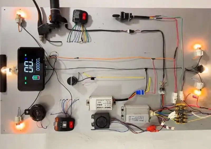
Electric Bicycle Electrical Faults: A General Troubleshooting Procedure That Works
Electric bicycle faults come in every shape and size. The bike completely dead with no response. The display dark. The motor refusing to turn, or turning and refusing to stop. When these symptoms appear, the first instinct is often to tear into the controller or replace the motor. That costs money and still may not find the cause. There is a better way in: e-bike troubleshooting follows one general procedure. Whatever the surface symptom, you work the same trunk: fit the battery, check the display, power up the system, test the motor, isolate the throttle and brake cut-off levers, then check wiring and connections, one stage at a time. Start with the simplest checks and work inward. This article walks that trunk from end to end, following the diagnostic flowchart.
Diagnostic Flowchart
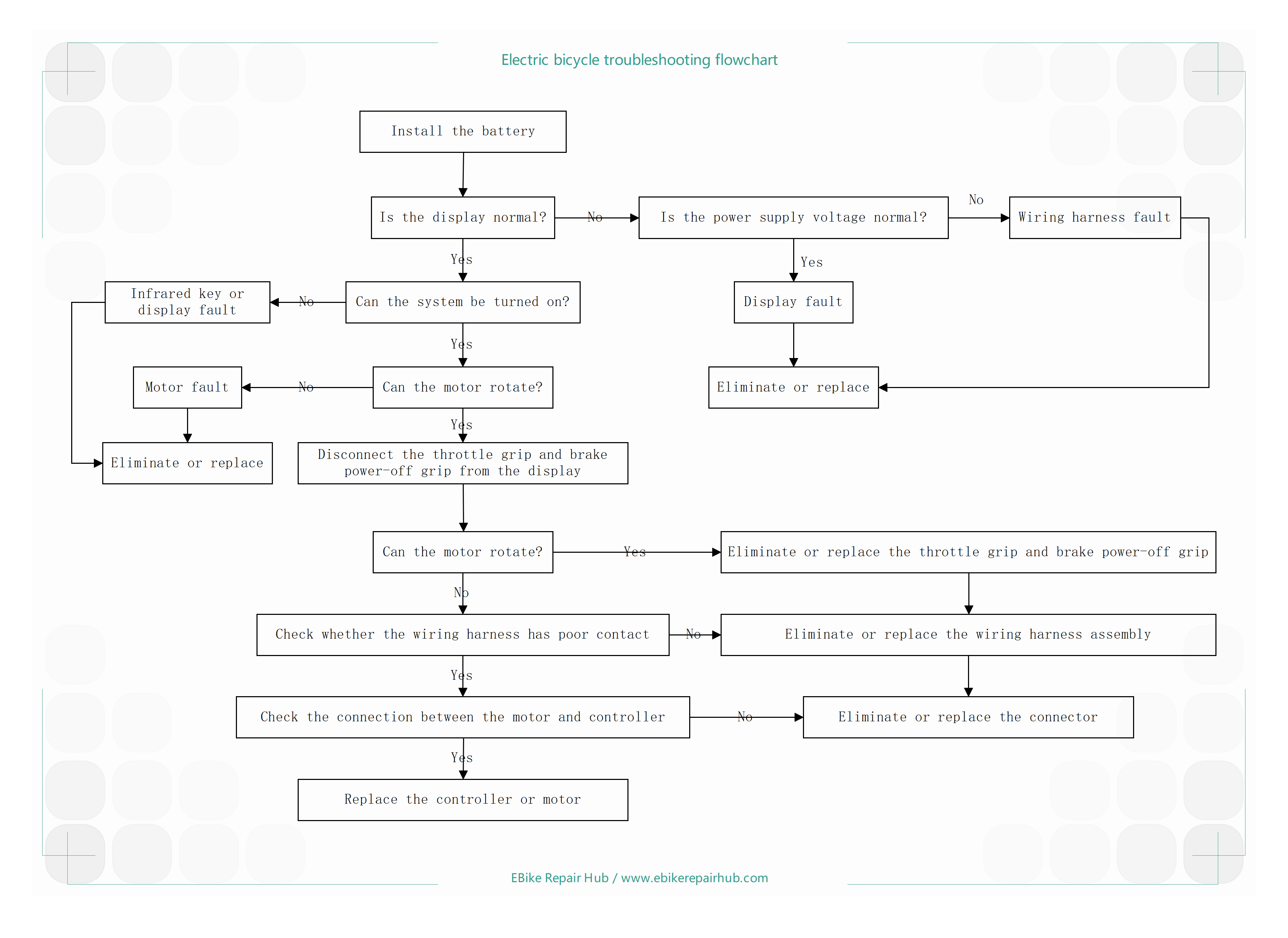
Each section below covers one stage of the chart.
1. Starting Point: Fit the Battery, Then Look at the Display
Every repair starts at the power supply. Fit the battery, confirm it is charged, and check that the contacts are clean and tight. Then look at the display. The display is the face of the whole vehicle: whether it lights up, and whether its readings make sense, tells you a great deal about the state of the power path before you have touched a single tool.
If the display is normal, the supply path from battery to display is essentially sound, and you move on to the next question: can the system be switched on?
If the display is abnormal, resist the urge to condemn the display itself. Test the supply voltage first. If voltage is normal but the display shows nothing, the supply is fine and the display is the problem. If voltage is abnormal, power is not arriving at all, which points at the wiring harness: check the supply wiring for open circuits, shorts, and poor contact. In the chart, both conclusions run into the same terminal box: rectify or replace.
This single check prevents more unnecessary display replacements than any other step in the procedure. A dark display looks exactly like a dead display, and the only way to tell them apart is a voltage reading.
2. Can the System Be Switched On: Infrared Key and Display Check
Display normal. Now try to switch the system on, by key or by infrared remote.
If it switches on, the control circuit powers up correctly and you move to the motor test.
If it does not, the fault sits with the infrared key or the display. On models with infrared anti-theft or remote functions, a failed key and damaged control circuitry inside the display produce the same symptom. Check in order: try the spare key, re-pair the one you have, then inspect the receiver circuit at the display end. If confirmed faulty, rectify or replace the part. (One quirk of the printed chart: the arrow from this box to the shared “rectify or replace” terminal is easy to miss, but the logic of the procedure puts it there.)
3. Does the Motor Turn: Judging the Motor Itself
System on, twist the throttle, and watch the motor.
If the motor does not turn, the conclusion is a motor fault, which should be rectified or replaced. The detailed checks depend on the motor type. Brushed motors: carbon brushes, windings, commutator. Brushless motors: Hall sensor supply and signals, covered step by step in the brushless motor article of this series.
If the motor does turn, the main drive chain is essentially working. But turning is not the same as healthy. If the actual symptom is abnormal rotation, running you cannot stop, or behavior that comes and goes, keep going down the chart; the isolation checks below are where those faults get caught.
4. The Isolation Test: Disconnect Throttle, Brake Cut-Off Lever, and Display
This is the most skillful move in the whole procedure. Disconnect the throttle, the brake cut-off lever, and the display from the controller, then ask the same question again: does the motor turn?
If the motor now turns with its command signals removed, something on the signal side is stuck “on.” The conclusion is a throttle or brake cut-off lever fault, typically an internal short in the throttle or a jammed signal; rectify or replace those parts. This is exactly how a “runs non-stop” complaint gets pinned down. On the chart, this action box also leads onward to the wiring harness assembly and then the connectors, so if new levers do not end the problem, the chain tells you where to go next.
If the motor still does not turn, the signal side is clear and the problem lives in the motor supply wiring or connections, which is stage five.
The logic applies to every electrical fault: remove a suspect and watch whether the system’s behavior changes. If it changes, the part you removed was the culprit. If it does not, the culprit is somewhere else. Disconnecting three signal components at once settles three categories of suspicion with a single test.
Repair tip: There are many components involved when a motor fails to turn, and there are numerous connections as well. This is especially true for older electric bikes, where connections that were previously fine may develop poor contact due to pulling or twisting during the repair process. This can ultimately cause the motor to fail to start. Therefore, inspect every connection patiently and carefully; reconnect any suspicious connections.
5. Wiring and Connections: the Last Two Stages
Stage one asks: is the wiring harness making poor contact? If no poor contact is found, and every earlier possibility has already been ruled out, rectify or replace the wiring harness assembly, which on the chart leads to the connectors. If poor contact is found, deal with it, then continue to stage two.
Stage two asks: how is the motor-to-controller connection? Loose, corroded, or burnt plugs mean the connection is abnormal; rectify or replace the connectors. A sound connection leaves only the two core components in the entire system, and the chart ends where every technician ends: replace the controller or the motor, verified one at a time by substitution. Fit a known-good controller first. If the fault is still there, move to the motor.
Substitution is the last resort of the whole procedure, and it is only justified at this point in the chart. Swapping parts before the earlier stages have done their work is how repair bills double and faults survive.
6. The Thinking Behind the Procedure, and Safety Notes
Read as a whole, the chart embodies three habits that outlive this one procedure:
- Sequence. Power supply first, then control, then actuation, then signals and wiring. Source to end, never doubling back.
- Isolation. Remove a suspect, watch the system. One test, one category eliminated.
- Substitution. Only when everything measurable has been measured, verify with known-good parts.
Safety notes: switch off the power and take the key out before starting; never unplug connectors on a live circuit; replace fuses only with the original rating; when testing motor rotation, put the bike on its stand and keep clear of rotating parts; replacement controllers must match the original voltage and power rating; and if soldering and motor assembly are not things you have done before, leave that work to a repair shop.
7. Summary
The whole procedure in one paragraph. Fit the battery and look at the display; if the display is dark, measure the supply voltage before blaming anything. Display fine but system dead, work through key and receiver. Motor silent with the system on, judge the motor by type. Motor running when it shouldn’t, or symptoms that come and go, disconnect throttle, brake lever, and display and watch what changes. Everything downstream of that is wiring, connectors, and finally the substitution of controller or motor. Work the trunk in order, stop at the first fault you can confirm, and most of these bikes are diagnosed within a quarter of an hour.
This guide covers one branch of the general e-bike electrical fault diagnosis process. For the complete flowchart and broader troubleshooting framework, see our main guide: E-Bike Repair Overview: Fault Diagnosis & Repair Methods →