
Motor Won’t Run, or Won’t Stop Running: One Flowchart for Both
Electric bicycle motor faults include two symptoms that look like exact opposites. In one, the motor will not run: you twist the throttle and nothing happens. In the other, it runs non-stop: you never touched the throttle, yet the motor spins the moment power goes on and may refuse to stop. The first leaves you pushing the bike home. The second is a safety problem, and the power should come off before anything else. Opposite as they look, both live on the same drive chain, and one diagnostic flowchart covers both. The first move is always to identify which symptom you have, then follow that branch. The rest of this article walks the chart branch by branch, with the test, the verdict, and the fix for each step.
Diagnostic Flowchart
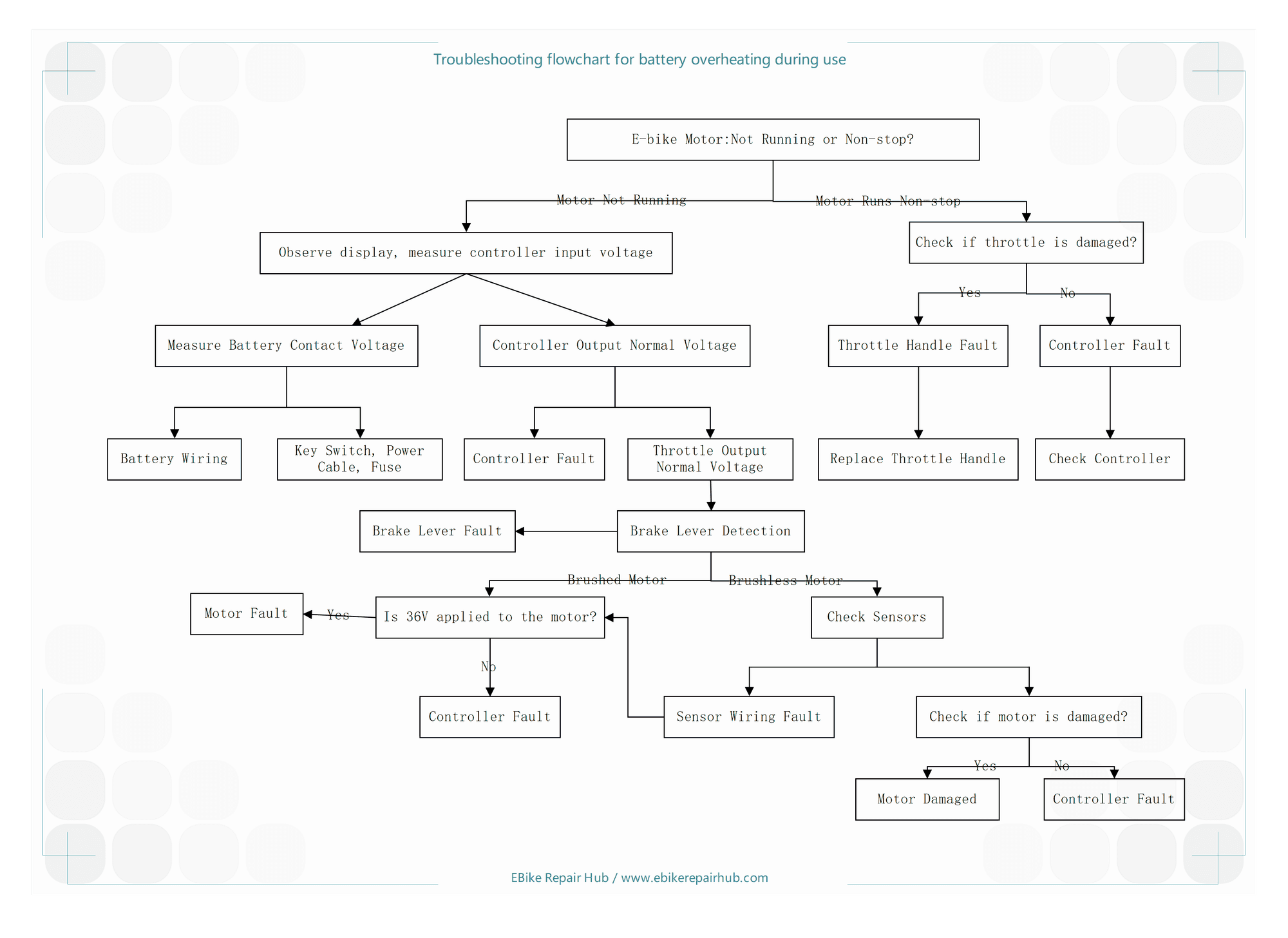
The flowchart below maps the whole procedure. Each section that follows expands one part of it.
1. Why Two Opposite Faults Share One Flowchart
The drive chain of an electric bicycle is a single path: battery → key switch/fuse → controller → motor. The throttle sits alongside it as the commander, sending speed signals to the controller. Both symptoms come from this same chain, in opposite directions.
When the motor won’t run, something in the chain is broken: power never arrives, the controller produces no output, the brake lever cut-off switch has triggered when it shouldn’t, or the motor itself is dead.
When the motor runs non-stop, the chain is stuck conducting. Usually that means a damaged throttle whose signal never drops from full speed, or power transistors inside the controller that have shorted and pass current the instant power is switched on.
That is why the chart opens with a triage question: confirm whether the symptom is “won’t run” or “runs non-stop,” and only then enter the matching branch. One warning before you touch anything on the non-stop side: key off, bike on its center stand, wheel clear of the ground. A wheel that starts spinning on its own mid-repair is how fingers and garage doors get hurt.
2. The “Runs Non-Stop” Branch: Throttle First, Controller Second
Step 1: check the throttle. Inside the grip is a Hall element or a potentiometer. Normally, releasing the throttle drops the signal voltage to its minimum and the controller commands zero speed. Three failures defeat this: an internal short, a jammed magnet, or a signal wire bonded to the supply. Any of them holds the signal high permanently, and the controller reacts exactly as it should to a wide-open throttle. It just never gets told otherwise. This is the most common cause of a motor that runs non-stop.
If the throttle is damaged, replace the grip. When fitting the new one, keep the wire order straight: red is supply, black is ground, green or blue is signal. Reversed wiring can produce runaway acceleration the moment you power up, which is a much worse problem than the one you started with.
If the throttle checks out fine, the fault moves to the controller, and the usual suspect is shorted output transistors that have lost all control of the motor feed. Check it with the power off: look for burn marks, smell for burnt insulation, and if needed test with a multimeter whether the output terminals conduct when they shouldn’t. Confirmed faulty, replace it with a controller of identical specifications.
Emergency measure: This kind of problem usually sits in the throttle grip itself. On the spot, you can lay the bike flat on its side, then work the throttle grip back and forth forcefully by hand, or tap the grip and the area around it with a hard object. The point is to shake loose whatever is shorted or jammed inside. One rule to remember once the fault clears: do not twist the throttle again, and replace the grip as soon as you can. The problem will come back if you don’t.
3. The “Motor Won’t Run” Branch: Start at the Input Voltage
Step 1: look at the display, then measure the controller input. Key on. Does the dashboard or battery-level display light up? A dark display means power is not even reaching the control system, and the hunt starts at the battery end. If the display works but the motor stays still, set the multimeter to DC volts and measure the controller’s input terminals to confirm battery voltage actually arrives there.
From that point the chart splits into two paths.
Path 1: battery contact voltage. Measure straight at the battery output contacts. No voltage, or clearly low, and you work along the supply path one item at a time. Battery wiring first: pack leads and plug contacts go loose, oxidize, and corrode, so retighten and clean whatever you find. Then the key switch, power cord, and fuse: switch contacts can fail to conduct, cords break internally, and fuses blow. A blown fuse gets replaced with one of the same rating, and you should also ask why it blew, because a short circuit that melted a fuse will melt the next one too. Never put copper wire in a fuse holder.
Path 2: controller output. With correct input voltage, measure the controller’s output terminals. Abnormal or missing output means the controller is faulty; repair or replace it. Normal output means the controller is doing its job, and the problem sits in the signal stage or further downstream. Check the throttle output voltage next: a signal with no variation, or one stuck at zero, calls for throttle repair or replacement. A healthy throttle signal sends you to the brake lever test.
4. The Brake Lever Test and What Follows It
Brake levers carry a cut-off switch that tells the controller to remove power whenever you brake. The switch can stick, corrode shut, or short in its wiring, and then the controller stays in brake cut-off mode no matter what the throttle says. The test takes one minute: unplug the brake lever cut-off connector and try the throttle again. Motor runs now, and you have found a brake lever fault; adjust or replace the lever or its switch.
With the brake levers ruled out, the path divides by motor type.
Brushed motor: is 36 V reaching the motor? Twist the throttle and measure at the motor terminals (36 V system shown here as an example). If the drive voltage arrives but the motor does not turn, the fault is inside the motor: worn-out carbon brushes, a jammed brush holder, or an open winding. Repair or replace the motor. If the voltage never arrives, look between controller and motor: the connecting leads first, then the controller’s output transistors.
Brushless motor: test the sensors. A brushless motor runs on position reports from three switch-type Hall components; without them the controller cannot commutate, and the motor either stays still or jerks. Key on, measure the sensor supply between the red and black wires first. It should read 5 V, 10 V, or 15 V depending on the controller; a wrong reading indicts the controller itself. Supply good, then turn the motor slowly by hand and watch each of the three signal wires: every one should switch regularly between 0 V and the supply voltage. A signal that never switches indicates a failed Hall sensor. Replace the Hall components, or the motor.
5. Safety Notes
- On a “runs non-stop” fault: key off, put the bike on its center stand, wheel off the ground, before anything else.
- Cut power before unplugging connectors or touching wiring. Never short a live circuit.
- Fuses get replaced with the original rating. Copper and iron wire are not fuses.
- A controller housing that is hot or smells burnt gets its power cut and no further testing.
- Replacement controllers must match the original voltage and power rating. If you have never opened a motor or soldered inside one, leave that work to a repair shop.
6. Summary
Two symptoms, one chart, one habit: triage first. A motor that runs non-stop is a throttle question before it is a controller question. A motor that won’t run is an input-voltage question before it is an output question, and a brake-lever question before it is a motor question. Every step in the chart has a plain pass/fail reading, so work the branches in order and stop at the first fault you can prove. The component that fails the test is the one you replace.
For motor testing methods and repair case analysis, see E-Bike Motor Testing & Repair: 23 Case Studies.