
Brushless Motor Not Running: How to Find the Fault Step by Step
Turn the key, twist the throttle, the display lights up, and the motor does nothing. If you work on e-bikes, you have seen this one dozens of times. A brushless motor has no carbon brushes and no commutator to blame, so the usual suspects don’t apply. It runs entirely on the cooperation between the Hall sensors and the controller, and when the motor stays still, something in that partnership has broken.
The worst response is swapping parts at random. It costs money, it costs time, and half the time the new part was never the problem. The better way is to understand how the system is supposed to work, then follow the flowchart below and isolate the fault in order: outside first, signals before components.
Diagnostic Flowchart
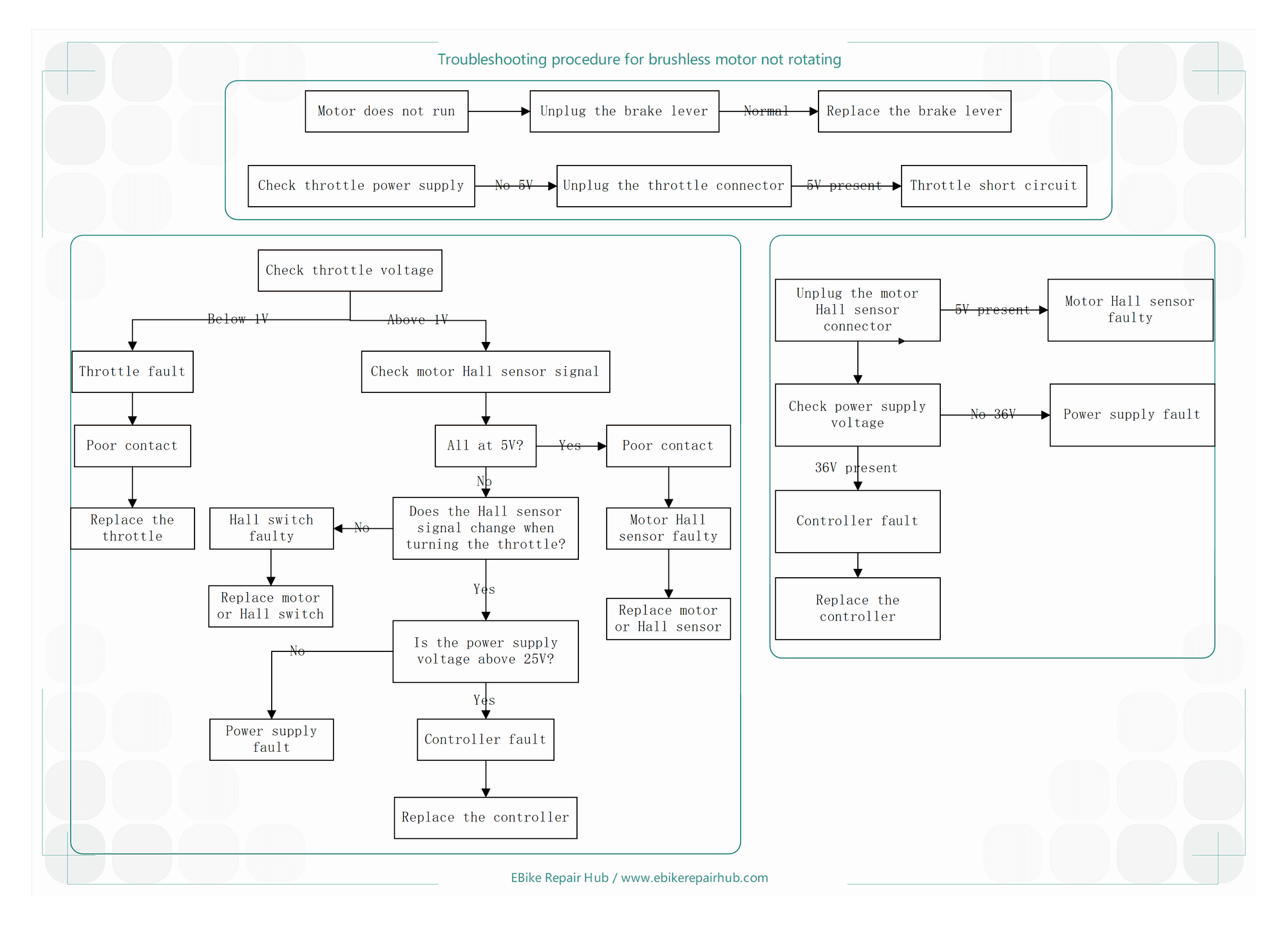
Each section below walks through one part of this chart.
1. How a Brushless Motor Actually Turns
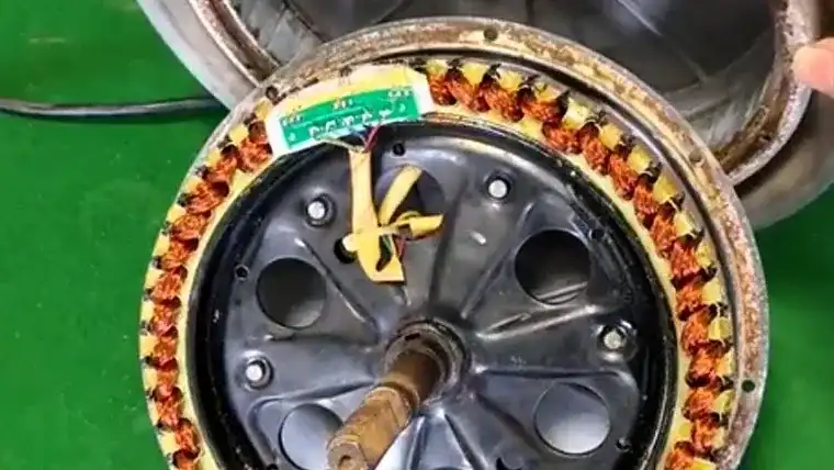
The sensor assembly inside the motor is made of three switch-type Hall components mounted on the stator. Their only job is to report where the rotor magnets are. The controller reads those three signals and fires its internal power transistors in sequence, so current flows through the stator coils in a repeating pattern. That pattern makes a rotating magnetic field, and the field drags the rotor around with it.
The whole chain looks like this: magnet position → Hall signal → controller switches → coil current → rotation.
When the motor won’t run, exactly one kind of thing has happened: some link in that chain is broken. Either the signal never leaves the motor (dead Hall sensor, corroded wiring contact), or it leaves but the controller ignores it (controller fault), or the controller drives but the power never reaches the coils (broken or loose phase wires). Every test in this article checks one of those three links, and nothing else.
2. Two Quick Checks Before You Touch the Multimeter
The flowchart starts with two branches that take five minutes and rule out the most embarrassing causes. Do these first.
The brake lever cut-off. Brake levers carry a cut-off switch that kills motor power when you brake. These switches stick, corrode, and trigger falsely more often than you’d think. When one sticks, the controller sits there receiving a “braking” signal forever and refuses to drive the motor. Unplug the brake lever cut-off connector and twist the throttle. If the motor now runs, the lever or its switch was the whole problem. Replace the lever.
The throttle supply. Set the multimeter to DC volts and check the throttle’s supply pins. No 5 V? Unplug the throttle connector and measure again at the controller end. If 5 V comes back with the throttle disconnected, the throttle is shorting the supply internally. Replace it. If the controller end still shows nothing, the fault is inside the controller’s power section, and you can skip ahead to Section 3 with low expectations.
3. Sensor Supply Voltage: Is the Controller Feeding the Halls?
This is the first real measurement, and it answers one question: is the controller able to power the Hall sensors at all?
Turn on the key switch. Find the five sensor wires coming out of the controller: one supply positive, one negative, three signal wires. Measure between the red (+) and black (−) wires.
You should read 5 V, 10 V, or 15 V. Which one is correct depends on the controller model, so all three are legitimate answers. Check against the rating of the controller on your particular bike rather than assuming 5 V.
If the reading is missing or clearly off the rated value, stop here. The controller cannot power the Hall sensors, which makes every signal test downstream meaningless. Repair or replace the controller.
4. The Hall Signal Test: Do the Sensors Actually Switch?
Supply voltage is good. Now check whether the three Hall components do their job.
Keep the power on and slowly rotate the motor by turning the wheel. Back-probe each of the three signal wires and watch the meter. Each signal should flip regularly between 0 V and the supply voltage (5, 10, or 15 V, whatever you measured in Section 3). Every time the rotor advances, a magnet passes a different Hall component and its output flips. That flipping is the commutation information the controller lives on.
A signal that never moves tells you which part is dead. Stuck at 0 V or stuck at full supply voltage, or flipping irregularly while the others behave: the sensor assembly is faulty. Replace the Hall components if you can solder and open the motor correctly; otherwise replace the motor assembly.
5. The Three Phase Wires: The Last Suspect
Sensor supply correct, all three Hall signals switching, motor still silent. Only one place left: the three thick phase wires between controller and motor.
Power off. Check that all three are seated firmly at the controller output terminals. Look at the connectors closely for burn marks, melted plastic, green corrosion, or pins that have backed out. Then run your hands along the wire length looking for cuts, kinks, and crushed sections, especially where the harness passes the axle.
If a lead is damaged, the fix depends on where: reconnect the lead from inside the motor if the break is at the motor end, or replace the lead entirely. Once the three-phase path is restored, the motor runs.
Fault analysis: burnt phase wires shorting at the terminals are usually the result of sustained overload, and this pattern shows up more often on electric tricycles. After the repair, keep the vehicle out of long-term overload conditions, or the same connector will burn again.
6. Quick Recap
Motor stays still? Work in this order. Unplug the brake lever connector and check the throttle’s 5 V supply first — five minutes that rule out the two most common false alarms. Then measure the sensor supply between the red and black wires: 5, 10, or 15 V depending on the controller, and no voltage at all means the controller. Supply good? Rotate the wheel and watch the three Hall signals flip between 0 V and full supply. Any signal that refuses to move is a dead sensor. Signals healthy and the motor still silent, and there is only one suspect left: the three thick phase wires, so go look for burnt or loose connectors. Confirm each step before moving on, and stop at the first fault you can prove.
7. How the Flowchart Fits Together
Reading the chart as a whole, there are three paths and they cover each other’s blind spots.
The main flow runs: throttle voltage first (below 1 V means a throttle fault, usually poor contact; above 1 V, move on) → Hall sensor signals (all reading 5 V means poor contact or a dead sensor; no change when turning the throttle means a faulty Hall switch) → supply voltage (not above 25 V is a power supply fault; above 25 V with everything else normal is a controller fault).
The independent branch is a shortcut: unplug the motor Hall connector, and if 5 V is present at the supply pin, the controller side is fine and suspicion moves to the motor. Then check the main supply: no 36 V is a power fault; 36 V present with a dead motor points at the controller.
The two quick lines at the top (brake lever, throttle supply) are the pre-filter. Running them first is what keeps you from replacing a controller over a stuck brake switch.
8. Safety Notes
- Turn the key off before unplugging connectors or disconnecting leads. Never work a circuit live.
- When probing, touch only the target pin. Bridging two adjacent contacts with a probe tip is how controllers die mid-diagnosis.
- If the controller housing is hot to the touch or smells burnt, cut power and stop. Don’t keep testing it.
- Replacement controllers must match the original voltage and power rating.
- Replacing Hall components means opening the motor. If you haven’t soldered and reassembled one before, let a repair shop do it. A misaligned stator plate causes problems that are much harder to diagnose than the one you started with.
For motor testing methods and repair case analysis, see our main guide: E-Bike Motor Testing & Repair: 23 Case Studies