
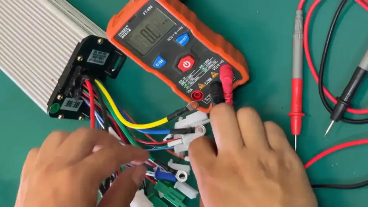
Electric Bicycle Controller Fault Repair Experience: Testing, Diagnosis, and Repair Case Analysis
The controller is the central component of an electric bicycle’s electrical system. Its main chips, key components, and peripheral devices are mounted on a single circuit board, so controller faults are located on the board. This guide covers controller testing and troubleshooting in four parts: testing the controller and Hall-effect sensors, diagnosing controller faults, component-level repair, and a large collection of real repair cases. Each case is presented from fault symptom to repair, covering brushed and brushless controllers, MOSFET and Hall sensor failures, power supply faults, and controller replacement procedures. Because controller testing involves live circuits and sensitive components, always follow the safety notes in each section before opening the enclosure or probing the board.
Electric Bicycle Controller Testing and Troubleshooting
The central component of the controller is the circuit board; all main chips, key components, and peripheral devices are mounted on a single board. Therefore, all controller malfunctions originate on the circuit board.
Circuit board faults are classified into three types: port-related faults, functional faults, and parameter-related faults. Among these, port-related faults are easy to repair, functional faults are more complicated, and parameter-related faults cannot be repaired. Controller faults are difficult to repair; generally, only a loose solder joint can be identified and re-soldered. If a brushless motor is found to be rotating abnormally, and diagnosis confirms phase-loss operation, this indicates that a power transistor has burned out. Phase-loss operation caused by a burned-out power transistor produces a rough pulsation through the handlebars and the bike frame; continuing to operate the bike may cause additional power transistors to burn out. In such cases, the bike should be repaired or replaced at an authorized service center.
By measuring the power or signal voltage at the controller’s connection points or leads, you can analyze and pinpoint the location of the faulty component. The main symptoms of controller failure include the following:
a. Damage to power devices. Primary causes include: motor damage; poor quality or insufficiently rated power devices; loose components due to installation issues or vibration; motor overload; or damage to the power device drive circuit or unreasonable parameter design.
b. Failure of the controller’s internal power supply. Main causes include: short circuits in the controller’s internal circuitry; short circuits in peripheral control components; or short circuits in external leads.
c. Intermittent controller operation. The main causes include: parameter drift in the components themselves under high or low temperature conditions; high overall power consumption in the controller’s design, leading to localized overheating of certain components and triggering their protection mechanisms; and poor electrical contact.
d. Signal loss in the controller caused by worn connecting wires or faulty or disconnected connectors. The main causes include: inappropriate wire selection; inadequate wire protection; poor connector selection; and loose crimping of the wiring harness to the connectors.
If you are unfamiliar with the controller’s circuitry, do not open the enclosure yourself, and especially do not test it with a multimeter while the system is energized, as this is extremely dangerous and may cause further damage.
1. Testing the Controller and Hall Effect Sensors
1.1 Determining the Controller’s Undervoltage Threshold
As shown in Figure 1, connect a variable resistor in series with the battery and the controller. While the motor is running, adjust the variable resistor; if the motor stops momentarily, that point is the undervoltage protection threshold.
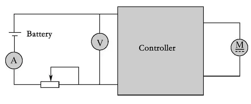
Figure 1: Controller Testing Diagram
1.2 Identifying and Replacing Hall Elements in Position Sensors
1.2.1 Identifying Hall Elements There are three methods for identifying Hall elements:
a. Identification Method 1:
① Connect the motor to a fully functional controller, turn on the power, and under no circumstances turn the throttle directly.
② Set the multimeter to the 20V DC voltage range. Connect the negative terminal (black probe) to the thin black wire among the five motor Hall sensor wires, and connect the positive terminal (red probe) to the thin red wire among the five motor Hall sensor wires. Measure the sensor supply voltage, which is typically 5V, though some may be 4.5V, 6.25V, etc. We will use 4.5V as an example here.
③ Connect the black probe to the black wire and the red probe to the yellow wire. Slowly rotate the motor while observing the multimeter reading; it should vary sequentially from 0 to 4.5V—this is normal. If the reading remains consistently high at 4.5V or consistently low at 0V, it indicates that the sensor corresponding to the yellow wire is damaged.
④ Follow step ③ to test the sensors corresponding to the green and blue wires separately and make a determination.
b. Identification Method 2:
① Unplug the motor controller connector and set the multimeter to the diode test range.
② Connect the multimeter’s red probe to the black wire and the black probe to the yellow, green, and blue Hall effect wires, respectively; the resistance values for all three should be essentially the same. Then swap the probes and test each wire individually; if the resistance values for any three wires differ, the corresponding sensor is faulty.
c. Identification Method 3:
Insert the Hall element into a three-pin socket designed for transistors in the order of pins 1, 2, and 3. Then connect the power supply, use the multimeter to measure the voltage between pins 2 and 3, and check the output voltage. Next, bring one pole of a magnet close to the front of the Hall element and observe the multimeter’s output voltage. Then, bring the other pole of the magnet close to it; if the output voltage fluctuates, it indicates that the Hall effect sensor is functioning properly; if the voltage remains unchanged, connect pins 1 and 3 to the multimeter and repeat the above procedure. If the voltage still remains unchanged, it indicates that the Hall effect sensor is damaged.
1.2.2 Replacing the Hall Effect Sensor
a. Remove the end caps on both sides and take the stator out of the hub.
b. Cut off the lead of the sensor determined to be damaged from the end closest to the circuit board and ensure they do not touch each other.
c. Chisel the damaged sensor off the stator, taking care not to damage the enameled wire. After cleaning the groove, secure the new sensor in the groove with AB adhesive, paying attention to the sensor’s front and back sides.
d. Solder the sensor leads to their corresponding pads and trim off any excess leads.
e. Use waxed thread to secure the sensor and circuit board to the stator.
f. Carefully place the stator into the hub, fit the end caps, and reassemble the motor.
To ensure the accuracy of the motor’s commutation positions, all three Hall effect sensors should generally be replaced at the same time. Before replacing the Hall effect sensors, you must determine whether the motor’s phase angle is 120° or 60°. Generally, in a 60° phase angle motor, the three Hall elements are arranged in parallel. In a 120° phase angle motor, however, the middle Hall element is oriented 180° out of phase with the others.
Recheck using the identification method, and after confirming everything is correct, test the motor.
For insulation degradation caused by water ingress into the motor, set the multimeter set to the 200 MΩ resistance range to measure the resistance between the motor’s phase wires and the shaft; the normal reading should be ∞. If the multimeter displays a value, disassemble the motor to drain the water, then dry it using a hair dryer or by exposing it to sunlight. Measure the resistance again until it returns to normal. Next, use the diagnostic method to check the sensors; if any are damaged, replace it.
2. Diagnosis and Troubleshooting of Controller Faults
2.1 Quick Check for Controller Functionality
The quick check method for controller functionality is as follows:
a. Check for any unusual odors coming from the controller.
b. For brushed controllers, rotate the throttle grip and use a multimeter to measure whether there is voltage at the controller’s output terminals.
c. With all connections secure, turn on the power and check whether the motor is difficult to engage (for brushless controllers).
d. Use a multimeter set to the resistance range to check for open circuits in the controller’s wiring.
e. Use a multimeter set to the resistance range to check whether the resistance values of the controller’s power components are normal.
f. Use a multimeter to check whether the controller is producing speed control and power-off signals.
2.2 Diagnosis and Troubleshooting of Controller Faults
2.2.1 Diagnosis and Troubleshooting of Brushless Controller Faults
a. Causes of Faults. The main causes of brushless controller faults are as follows:
① Generally, brushless controllers only have undervoltage and overcurrent protection functions.
Undervoltage protection shuts off the motor during over-discharge to protect it, but it cannot monitor the voltage as it recovers, which can lead to battery over-discharge.
Additionally, component aging can cause localized short circuits in the controller, which may result in some controllers burning out.
② Poor intrinsic quality of the brushless controller. Since the controller relies on connecting wires to transmit signals, failures in lead wires, connectors, or power devices can cause the controller to malfunction; power devices tend to age and fail rapidly during use. Furthermore, poor heat dissipation from the controller housing leads to high internal temperatures, which can easily loosen the solder joints of internal components and cause controller damage.
b. Troubleshooting Methods. First, check the brake lever control wires (there is no need to disconnect the wires between the brake lever and the controller; simply touch the metal plate at the base of the wires with the multimeter probes). In electric bicycles that typically use low-level braking, the two wires from the brake lever are in a high-level state; when the brake lever is squeezed, the voltage between the two wires should be 0V.
Next, check the throttle voltage: For e-bikes with forward-throttle control, the voltage increases as the throttle is turned (for reverse-throttle control, the voltage decreases), up to a maximum of 5V; the starting voltage varies, typically 2.5V. Additionally, the PWM chip should output drive pulses, and the voltage at the output line terminals should match the power supply voltage.
If both the brake lever and throttle lever are functioning normally but there is no voltage output, this indicates a controller malfunction, and further inspection is required.
2.2.2 Diagnosis and Troubleshooting of Brushed Controllers The core circuitry of a brushed controller consists of an oscillator, pulse width modulation (PWM), and other components. Currently, the components comprising the core circuit fall into three major categories: ① Standard voltage comparators, primarily the LM339; the LM339 is a quad comparator with a very low failure rate; ② Dedicated pulse-width modulation (PWM) chips; the most commonly used is the TL494. A common configuration is the TL494 paired with the LM358, which is a dual operational amplifier. Other configurations include the SG3525 and MC33035; the MC33035 was originally designed as a dedicated chip for brushless controllers, but due to its mature technology and simple peripheral circuitry, it can also be used in brushed controllers, utilizing only one phase; ③ Microcontrollers: The microcontrollers most commonly used in brushed controllers include the Atmel 89C2051, a popular choice due to its good value. For brushless controllers, the Microchip 16C72 and 16F72 are the most commonly used microcontrollers.
First, make a rough estimate of the damaged component based on the symptoms and rule out easily identifiable faults such as poor external connections to the controller. For example: runaway operation could be caused by a shorted VMOS, or it could be due to the ground terminal of the Hall-effect speed throttle being disconnected; failure to rotate when powered on could indicate a controller malfunction, or it could be due to a burned-out or loose external connection—particularly in areas such as the brake switch, ignition key, battery, or fuse; lack of power under load could be caused by a desoldered current-sensing resistor or a problem with the motor. Only after confirming that the fault lies within the controller should you open it up for inspection and repair.
a. Troubleshooting Approach. First, VMOS devices in the controller have a high failure rate; most failures involve breakdown between the drain and source (DS), causing the motor to spin at high speed as soon as power is applied. This can be verified by testing with a multimeter set to the resistance range while the power is off; replacing the device will resolve the issue. When replacing the VMOS, pay attention to insulation and heat dissipation; apply thermal grease and securely fasten the heat sink’s mounting hardware. Along with VMOS breakdown, other surrounding components may also be damaged, such as the PNP transistor in the complementary push-pull lower channel.
Second, check the regulated power supply. While powered on, verify that its output matches the rated regulated voltage. If there is no voltage, check the load for short circuits or other abnormalities. Additionally, for the TL494, although its internal circuitry is complex, checking key points is sufficient to assess the general condition.
Pin 14 of the TL494 is the +5V reference power supply output. If the power supply at pin 12 is correct but there is no +5V at pin 14, the chip is typically defective; pin 3 is also a key point—when it is at a high potential, the chip shuts off the output. If it is at a high potential, investigate the cause, such as undervoltage protection or malfunction of the Hall-effect speed control throttle.
You can also check key points in the rear section, such as whether the VMOS gate voltage changes in response to the rotation of the Hall-effect speed control throttle.
b. Component-Level Troubleshooting. Most controllers with internal damage can be repaired by replacing the faulty components. The three components with the highest failure rate in brushed controllers are the power switch transistor (VMOS), the three-terminal regulated power supply IC, and the freewheeling diode.
① Component Identification. Field-effect transistors, 78XX three-terminal voltage regulators, and common-cathode bipolar diodes all have the same appearance and are encapsulated. The identification methods are as follows:
Identifying the freewheeling diode: This is the easiest to identify, characterized by: the middle leg (N) is isolated and connected to one wire from the motor; this wire is also connected to the positive terminal of the power supply. When measured with a multimeter set to the R×1 resistance range, the resistance between this leg and the positive terminal of the power supply is 0; the two outer legs (P) are connected on the circuit board and connected to the other wire from the motor. When measured with a multimeter set to the resistance range, the resistance between both wires connected to the motor and between the P and N legs of the freewheeling diode is 0.
Identifying a VMOSFET: The middle pin (N) is the drain (D). On the circuit board, it is connected to the two pins (P) on either side of the freewheeling diode and to the wire from the motor that is not connected to the positive terminal of the power supply. The right pin next to the three pins is the source (S), which is connected to the current-sensing resistor; using a multimeter set to the R×1 resistance range, measure the resistance between it and ground—it should be 0.
Identifying a three-terminal voltage regulator: You can use the process of elimination. If there are three components with heat sinks, first identify the freewheeling diode and the VMOS, and the remaining component is the three-terminal voltage regulator; if there are four heat-sinked packaged components, they are typically two VMOS devices. First, identify the freewheeling diode, then identify the VMOS devices. The two VMOS devices are connected in parallel—that is, the middle leads are connected to each other on the circuit board, and the right leads are connected to each other on the circuit board—and the remaining component is the three-terminal voltage regulator. Here, the “right lead” refers to the situation where the component’s marked side faces the operator, with the leads pointing downward, the leg corresponding to the operator’s right hand.
All three-terminal voltage regulators used here are positive-polarity types, but there are fixed-voltage 78XX series and adjustable LM317 (or LM337) types. In the 78XX series, the middle pin is grounded, the left pin is the input, and the right pin is the output. The LM317 and LM337 do not have a direct ground pin, but they share the left pin as the adjustment pin (ADJ). The difference is that in the LM317, the right pin is the input and the middle pin is the output; in the LM337, the middle pin is the input and the right pin is the output.
Although both VMOS and the 78XX three-terminal voltage regulator have one pin grounded, the VMOS power switch connects to the motor, whereas the 78XX voltage regulator does not. Integrated circuits can also be distinguished by characteristics such as the number of pins and connection points. For example: the TL494 has 16 pins, the LM324 and LM339 have 14 pins, and the LM393 and LM358 have 8 pins. Although the LM324 and LM339 are both 14-pin devices, their power supply pins differ: the LM324 uses pins 4 and 11, while the LM339 uses pins 3 and 12.
A nickel-copper or copper wire with a diameter of 1 mm and a length of approximately 10 mm—this is typically a current-sensing resistor—with one end connected to the source (S) of the VD-MOS, and the other to the negative terminal of the battery (high-purity black). When the copper wire is exposed to heat, the solder joints can easily come loose, increasing contact resistance and potentially causing the previously mentioned fault where the motor runs normally under light loads but loses power under heavy loads.
Further distinction can be made along the signal path: the core component of a brushed controller is the PWM. Upstream of the PWM are two input signals—one is the triangular wave from the triangle wave generator, and the other is the speed signal from the Hall-effect speed throttle; the PWM output is driven to the VMOS gate.
Some units feature an adjustable resistor, which is typically used to adjust the sampling threshold for battery undervoltage protection. If there is another adjustable resistor, it is likely used to adjust the current limit value.
Once the locations and terminals of the three types of components mentioned above have been identified, further on-circuit testing to determine their condition is generally sufficient—usually, simply checking for short circuits is adequate.
② Component Testing Methods. To determine whether there is a short circuit between the drain (D) and source (S) of the VMOS, use an analog multimeter set to the resistance range (R×1). If, when measuring in both forward and reverse directions, the resistance between the middle pin (drain, D) and the right pin (source, S) is close to zero, this indicates that the VMOS is faulty.
To determine whether there is a short circuit between the P and N terminals of the freewheeling diode, use an analog multimeter set to the resistance range (R×1) to measure the two wires connected to the motor. With the motor disconnected, if the resistance is close to zero in both forward and reverse directions, it can be reasonably concluded that the three-terminal voltage regulator IC is faulty. “Forward” and “reverse” refer to swapping the red and black test leads.
To determine whether the three-terminal voltage regulator IC is shorted, use an analog multimeter set to the R×100 range to measure the resistance between the input terminal and ground, and between the output terminal and ground, respectively. If the resistance is close to zero in both directions, this indicates that the three-terminal voltage regulator IC is faulty.
If the model of the field-effect transistor is unclear, replace it based on the following guidelines: for 24V and 36V controllers, use an IRF3205 or IRF2807; for 48V controllers, use an STP75NF75 or IRF2807.
③ Precautions:
a. Maintain the original insulation; ensure that the insulating pads and spacers are properly installed.
b. Ensure proper heat dissipation by applying a small amount of white thermal grease between the components and the insulating pads, as well as between the heat sink and the insulating pads, and then tighten the mounting screws.
c. Along with the failure of the field-effect transistor, other components may also be damaged. The most common is the transistor that accelerates the turn-off of the field-effect transistor; this is typically a PNP bipolar transistor. The system can still function without it, but the field-effect transistor will overheat and is prone to damage. Common models include 2N5401, 8550, and 9012.
(3) Component-Level Repair of Brushless Controllers Component-level repair of brushless controllers is more challenging than that of brushed controllers, primarily due to the extensive use of integrated circuits, a large number of surface-mount components, and three pulse-width modulation (PWM) signals. You can refer to the repair methods for brushed controllers to address issues such as desoldered current-sampling resistors, burned-out circuit board traces, and damaged field-effect transistors.
Common brushless-specific chip combinations for brushless controllers include: MC33035 with IR2103 driver, MC33035 with discrete component driver; MC33033 with IR2103, MC33033 with discrete component driver; LB11820 with IR2103 driver, LB11820 paired with discrete components.
The MC33035 has 24 pins, the MC33033 has 20 pins, the LB11820 has 30 pins, and the IR2103 has 8 pins. If an IR2103 is used as the driver (to drive the circuit), three units are required for each controller. Additionally, the reference voltage supplied by the MC33035 and MC33033 to the Hall-effect speed throttle is 6.25V, while the LB11820 uses 5V.
For microcontroller-based systems, most microcontrollers operate at 5V and require a dedicated 5V regulated power supply; most failures result from a short circuit between the microcontroller’s power supply pin and ground, which damages the 5V regulated power supply.
Case Studies in Electric Bicycle Controller Repair
Case 01: Brushed Controller Control Component Power Supply Fault
Fault Symptoms:
The power supply for the control components of a brushed controller is not functioning.
Troubleshooting:
The internal power supply of a controller typically uses a three-terminal voltage regulator IC, such as the 7805, 7806, 7812, or 7815, with output voltages of 5V, 6V, 12V, and 15V, respectively. Set the multimeter to the DC voltage +20V range, then touch the black and red probes to the black and red wires of the throttle, respectively, to check if the multimeter readings match the nominal voltages. The voltage difference between them should not exceed 0.2V, as shown in Figure 2. Otherwise, this indicates a fault in the controller’s internal power supply. Generally, faults in brushed controllers can be resolved by replacing the three-terminal voltage regulator IC.
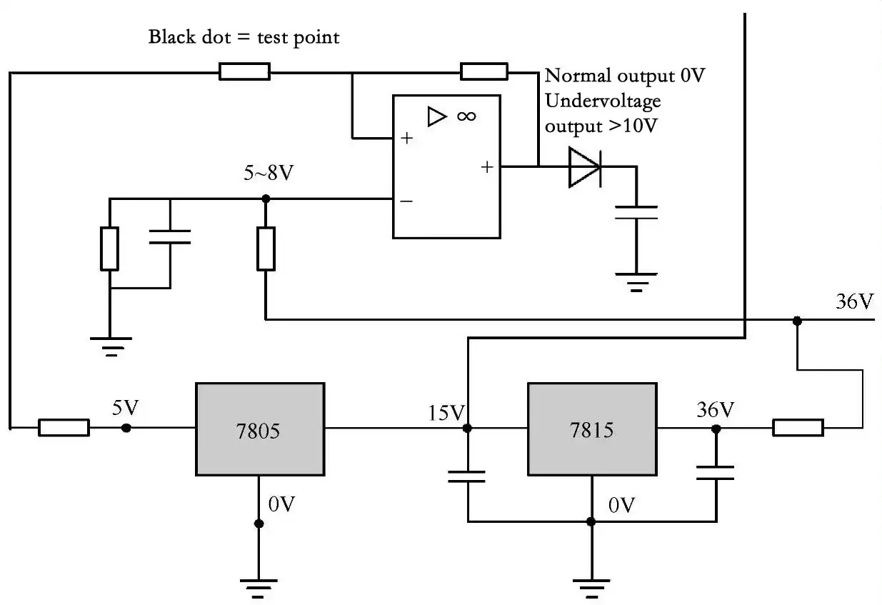
Figure 2: Measurement Points for Brushed Controller Power Supply Faults
Case 02: Brushless Controller Has No Output at All
Fault Symptoms:
The brushless controller has no output at all.
Troubleshooting:
Using a multimeter set to the +50V DC voltage range, check whether the gate voltages of the six MOSFETs correspond to the rotation angle of the throttle grip (see Table 1). If there is no correspondence, this indicates a fault in the controller’s PWM circuit or MOSFET driver circuit. Referring to the brushless controller main phase check diagram, measure whether the input and output pins correspond to the throttle rotation angle. This will help identify which chips are faulty. Replace them with chips of the same model to resolve the issue.
Table 1: Brushless Controller with No Output
| Chip Name | Model | Reference Voltage 6.25V | VCCG | ND Phase | Angle Adjustment | Sensor Input | Upper Transistor Drive | Lower Transistor Drive |
| Brushless Controller Chip | MC33033 | 7 | 14 | 13 | 18 | 4, 5, 6 | 2, 1, 20 | 17, 16, 15 |
| MC33035 | 8 | 17 | 16 | 22 | 2, 1, 24 | 21, 20, 19 | ||
| Brushless driver chips | IR2103(S) | 1 | 4 | 7 | 5 | |||
| IR2110 | 3 | 2 | 1 | |||||
| IR2113 | ||||||||
| IR2182(3/4) | 3 | 13 | 4 | |||||
| IR2130(2S) | 1 | 12 | 27, 23, 191 | 6, 15, 14 | ||||
| IR21844(S) | 7 | 5 | 12 | 6 |
Case 03: Runaway Motor
Fault Symptoms:
The motor spins as soon as the power is turned on, or the motor speed cannot be controlled by the throttle.
Troubleshooting:
A runaway motor occurs when the motor spins as soon as the power is turned on, or when the motor speed cannot be controlled by the throttle. This fault is generally caused by a shorted MOSFET. To determine if the MOSFET is faulty, use a multimeter set to the diode test mode to measure the three pins of the MOSFET; there should be no short circuit. If the MOSFET is damaged, the fault can be resolved by replacing it with a device of the same model.
Case 04: Controller Failure
Fault Symptoms:
The controller does not function properly.
Troubleshooting:
The main causes of electric bicycle controller failure are as follows:
① A short circuit in the controller circuit damages the power supply.
② Components operating at high or low temperatures may change performance parameters; or high power consumption by the controller, leading to localized overheating of certain components and triggering their built-in protection mechanisms; or poor electrical contact, resulting in controller malfunction.
③ Damage to the motor or poor-quality power devices; vibration or loosening of components; current overload; or damage to the power drive circuit, leading to failure of the power devices.
④ Inadequate protection of the controller wiring harness; loose crimping between the harness and connectors, resulting in wear on the connecting wires and poor contact or detachment of the connectors.
Therefore, it is essential to focus on improving the controller’s reliability, primarily through the following measures:
① Carefully screen the models and parameters of the power devices used in the controller, paying close attention to model numbers, brands, countries of origin, and suppliers.
② Design the power supply to operate on an independent power source; this prevents the controller from being damaged by short circuits in local circuits, and an abnormally high power supply voltage from damaging external components; a DC-DC module can be used for this purpose.
③ Select components with good temperature coefficients, modify the controller housing’s design to increase the heat dissipation area, and ensure adequate heat dissipation to prevent the controller from malfunctioning due to excessive heat. The housing material should preferably be thermally conductive.
④ Improve the controller’s connection wires and sleeve materials, and reduce sharp edges to enhance water resistance, abrasion resistance, dust resistance, vibration resistance, oxidation resistance, and wear resistance.
⑤ Connect the voltage monitoring and regulation circuit in parallel with the battery pack’s output terminals to monitor the startup voltage for undervoltage protection, and stabilize the voltage, thereby preventing the battery from over-discharging.
⑥ Install a current-limiting device or strictly control the setting of the controller’s overcurrent protection threshold (10–12 A) to ensure reliable protection for the battery and motor.
Case 05: No Voltage Output from the ZK3610A Brushed Controller
Fault Symptoms:
The ZK3610A brushed controller produces no voltage output.
Troubleshooting:
The circuit diagram of the ZK3610A brushed controller is shown in Figure 3. If the brushed controller fails to produce a voltage output, the troubleshooting procedure is as follows:
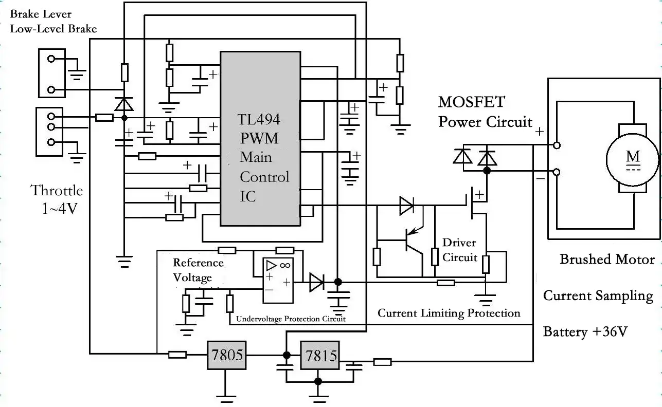
Figure 3: Circuit of the ZK3610A Brushed Controller
Set the multimeter to the 20V DC range and first check the high and low voltage levels of the throttle output signal. If the signal from the throttle lever shows a voltage change of more than 4V when the lever is squeezed, the throttle lever is functioning normally. Next, refer to the pin function table for commonly used chips in brushed controllers, compare the measured voltage values of the main control chip and logic chip, and verify whether the values of each chip’s peripheral components (resistors, capacitors, diodes) match the values marked on the components themselves to determine whether the fault lies with the peripheral components or the integrated circuits.
If the inspection reveals that control components are burned out, the main causes are: ① Reversal of the power supply’s positive and negative terminals during use; ② Water ingress into the controller causing a short circuit and burning out components; ③ Damage to components on the controller’s circuit board; ④ Solder joints on the circuit board have come loose or are faulty.
Repair the controller based on the causes listed above. If repair is not possible, replace the controller with one of the same model to resolve the issue.
Case 06: No Voltage Output from a Brushed Controller
Fault Symptoms:
The brushed controller produces no voltage output.
Troubleshooting:
When a brushed controller fails to output voltage, set the multimeter to the 20V DC range and check the high and low voltage levels of the brake lever’s output signal separately. If there is a voltage change of 4V or more when squeezing the brake lever, this indicates that the brake lever is functioning normally, and the controller should be inspected.
The specific troubleshooting method is as follows: See Table 2 for the pin functions of commonly used brushed controller chips. Check whether there is a corresponding relationship between the gate voltages of each MOSFET and the rotation angle of the throttle grip. Verify that the resistance and voltage values at key pins are normal, and inspect the external resistors and capacitors of each chip.
Table 2 Pin Functions of Commonly Used Brushed Controller Chips
| Chip Model | Power Supply | Ground | Signal Output | Signal Feedback | Non-Inverting Terminal | Inverting Terminal |
| LM239 | 3 | 12 | 14 | 13 | 8, 10 | 9, 12 |
| LN258 | 8 | 4 | 13 | 10 | 1, 3 | 8, 11 |
| LM324 | 4 | 11 | 7 | 6 | 1, 3 | 2, 5 |
| LM339 | 3 | 12 | 1 | 6 | 2, 5 | 4, 7 |
| IM358 | 8 | 4 | 7 | 6 | 1, 3 | 2, 5 |
| TL494 | 12 | 7 | 9, 10 | 3 | 1, 6 | 2, 15 |
Set the multimeter to the 50V DC voltage range and check whether the gate voltages of each MOSFET correspond to the rotation angle of the throttle. If there is no correlation, it indicates a fault in the PWM circuit or the MOSFET driver circuit within the controller.
Next, check whether the voltages at the IC’s input and output pins correspond to the throttle’s rotation angle. If there is no correspondence, the fault lies in the IC or related components.
Replace the damaged components listed above to resolve the fault.
Case 07: Phase Loss in a Brushless Controller
Fault Symptoms:
One phase of the controller’s three-phase circuit fails to function properly.
Troubleshooting:
Phase loss in a brushless controller refers to a situation where one phase of the controller’s three-phase circuit fails to function properly. Phase loss can be categorized as main-phase loss or Hall sensor phase loss.
(1) Main-Phase Loss: Troubleshooting for main-phase loss can be performed by referring to the procedures for brushed controllers. Check whether the MOSFETs are shorted. In a brushless controller, when MOSFETs are shorted, it typically involves a pair of MOSFETs (one above and one below) in the same phase shorting simultaneously; both should be replaced at the same time. The testing method for MOSFETs is as follows:
Use an HR-500 multimeter to check for short circuits in the resistance between the source and drain, gate and source, gate and drain, and between gates G1 and G2 of the field-effect transistor to determine whether the transistor is functional.
a. Measure the resistance between the source (S) and drain (D). To test, connect the two test leads between the source (S) and drain (D) terminals. Under normal conditions, the reading should remain constant between tens of ohms and several thousand ohms. Then, switch the test leads; the reading should remain unchanged; otherwise, the field-effect transistor is damaged.
b. Connect the multimeter probes between the S terminal and G1 (first gate), between the S terminal and G2 (second gate), and between G1 and G2, respectively. When swapping the probes, the resistance values obtained in each of the above cases should all be ∞. If the measured resistance values for any of these connections are too low or indicate a short circuit, it indicates that the field-effect transistor is damaged.
Note: If both the G1 and G2 terminals are open within the field-effect transistor, the resistance cannot be measured; in this case, use the substitution method for testing. If the MOSFET is found to be damaged, replace it with a device of the same model to resolve the fault. Appearance of a field-effect transistor is shown in Figure 4.
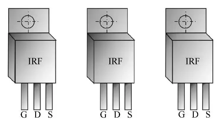
Figure 4: Appearance of a field-effect transistor
c. Testing Methods for Junction Field-Effect Transistors.
① Measure using an HR-500 multimeter. Set the multimeter to the R×10 or R×100 range. Connect the red and black test leads between the source (S) and drain (D) terminals of the field-effect transistor. Under normal conditions, the resistance should be between 10 and 100 Ω. Reverse the test leads and measure again; the resistance should match the previously measured value. Otherwise, it indicates that the transistor is damaged.
② Testing with an MF10 multimeter. Set the multimeter to the R×100k range, connect the black probe to the gate (G), and the red probe to the source (S). Apply a charge between the gate and source; at this point, the multimeter needle will deflect slightly. Then switch the multimeter to the R×1 range, connect the black probe to the drain (D), and the red probe to the source (S), under normal conditions, the meter’s needle should read a few ohms; if the resistance is too high, it indicates that the field-effect transistor is damaged.
d. Testing Method for VMOS Field-Effect Transistors. The specific testing procedure is as follows: Use an HR-500 multimeter to measure the resistance between the drain and source. Short-circuit the gate to the source, set the multimeter to the R×1 range, connect the black probe to the source, and the red probe to the drain. A measured resistance of a few ohms to tens of ohms indicates that the field-effect transistor is functional. Otherwise, it indicates that the field-effect transistor is damaged.
(2) Brushless Controller Hall Sensor Phase Loss A Hall sensor phase loss in a brushless controller manifests as the controller’s inability to recognize the motor’s Hall signal. The specific testing method is as follows:
Disconnect the Hall sensor leads between the controller and the brushless motor. With the controller powered on, set the multimeter to the +20V (DC) range, place the black probe on the controller’s Hall sensor lead, and use the red probe to test the other Hall sensor leads on the controller. A voltage of at least +5V should be present; otherwise, it indicates a fault in the controller’s internal Hall output circuit.
By testing the corresponding pins of the main control chip on the Hall lead filter capacitor, the exact location of the fault can be further determined. Replacing the filter capacitor or the main control chip will resolve the issue.
Using the voltage comparison method as shown in Figure 5, measuring the voltage at each labeled point allows you to identify the specific faulty component.
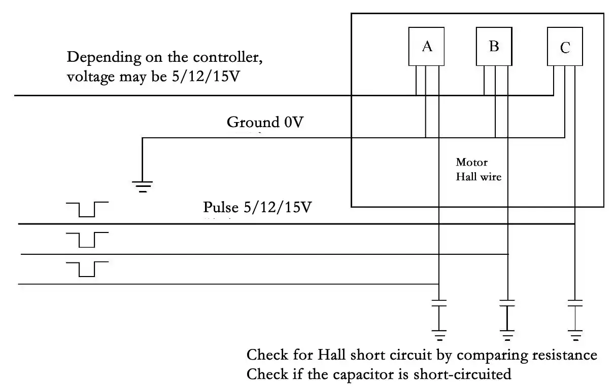
Figure 5: Brushless Controller Hall Sensor Phase Loss Check Diagram
Case 08: Runaway Motor
Fault Symptoms:
As soon as the power lock is released, the motor spins at high speed and the rotational speed cannot be controlled.
Troubleshooting:
A runaway motor in an electric bicycle refers to a phenomenon where, as soon as the power lock is released, the motor spins at high speed and the rotational speed cannot be controlled. Electric bicycles generally use PWM to regulate speed and implement various protective functions; their primary components are power MOSFETs, freewheeling diodes, and high-quality, high-capacity capacitors. When a MOSFET breaks down and conducts in the on-state, the motor becomes uncontrollable, and the inrush current during stalling can reach tens of amperes; even forced braking may fail to trip the fuse within a short period of time.
The main causes of the above fault are: ① The speed control throttle is not functioning; ② The controller is damaged. First, check whether the three wires connecting the speed control throttle to the controller are miswired. If so, reconnect them correctly; if the wiring is correct, this indicates a fault with the speed control twist grip; clean or replace the photosensitive film and wipe the phototransistor. If the fault persists, replace the speed control twist grip.
If the speed control twist grip is functioning normally, inspect the controller.
Use the diode test setting on a multimeter to check the three pins of the MOSFET; there should be no short circuit between any two pins. Otherwise, the MOSFET is damaged. Replace it with a field-effect transistor of the same model to resolve the issue.
If the bike runs out of control when braking, the primary cause is water entering the controller, preventing it from cutting off power and causing the bike to run out of control. Therefore, take care to keep the controller dry in everyday use; when washing the bike with water, ensure no water enters the controller to avoid short circuits in the circuitry.
To prevent runaway, high-quality key components should be selected during design, and any abnormalities should be addressed promptly. For example, the emergency shut-off switch used in Lvyuan electric bicycles can effectively prevent runaway.
Case 09: Motor Does Not Rotate or Suddenly Stops While Riding
Fault Symptoms:
When the power lock switch is turned on and the throttle is twisted, the motor does not rotate; or the motor suddenly stops while riding.
Troubleshooting:
If the motor fails to rotate when the power lock switch is turned on and the throttle is twisted, or if it suddenly stops while riding, first check whether the throttle wire is open or if there is poor contact at the connector.
Next, check whether the brake lever wire has an open circuit or a short circuit. If these are normal, the fault lies in a burned-out field-effect transistor in the controller, which is in an open-circuit state. Replace the field-effect transistor with one of the same model to resolve the issue.
Case 10: Electric Hub Cannot Be De-energized When Operating the Right Handlebar
Fault Symptoms:
When operating the right handlebar of an electric bicycle, the electric hub cannot be de-energized.
Troubleshooting:
When operating the right handlebar of an electric bicycle, the main reasons why the electric hub cannot be de-energized are: ① The handlebar pull cable has not returned to its original position; ② The brake cut-off switch is damaged; ③ The controller is burned out.
(1) Handlebar pull cable has not returned to its original position. If the handlebar pull cable has not returned to its original position, check whether the cable housing is jammed; if so, clear the obstruction.
(2) Brake power-off switch is damaged
a. For mechanical normally-open power-off switches, the cause of the power not shutting off is that the contact spring plate is not making contact with the contact point; it should be repaired; if repair is not possible, the brake power-off switch should be replaced.
b. For electronic low-voltage power-off switches, replacement is the only option.
A quick troubleshooting method is to short-circuit the controller’s output wires to ground. If power is cut off, the brake lever is faulty; if power remains on, it indicates a controller malfunction.
(3) Controller burnout: Short-circuit the purple and black wires at the controller’s output terminals. If the power does not cut off, the controller is faulty and should be replaced.
Case 11: Speed Control Failure or Low Speed
Fault Symptoms:
The speed control fails or the bike runs at low speed.
Troubleshooting:
The main causes of speed control failure or low speed are: ① Low battery voltage; ② Loose connection at the speed control grip or wires have come loose; ③ the throttle grip spring is jammed or has failed; ④ the controller is damaged.
Troubleshooting can be performed based on the different causes of failure listed above.
a. Check the battery. The voltage of a 24V battery should be between 23 and 26 V, and that of a 36V battery should be between 35 and 38 V. If the voltage is outside the specified range, recharge the battery promptly.
b. Check the speed control knob. When the voltage at the speed control knob is normal (no undervoltage), a broken reset spring and a break in the speed control wire will cause the speed control to fail. If the speed control knob does not reset freely, it should be replaced; alternatively, use a multimeter to check whether there is 5V between the red and black terminals of the three-pin connector and 4.8V between the black and green wires (when the speed control knob is turned to its limit). If the voltage is absent or too low, the speed control knob should also be replaced.
c. Test the controller. If the battery voltage is normal, use an electric bicycle tester to check the controller. Plug the controller’s 9-pin or 8-pin flat connector into the tester’s socket. If the controller’s output voltage or current is abnormal, replace the controller; if they are normal, this indicates a fault in the electric hub, which should be further inspected.
d. Excessive buildup of carbon dust in the brush motor hub chamber can cause the speed to slow down; remove the carbon dust to resolve the issue.
Case 12: Controller Replacement
Fault Symptoms:
The controller needs to be replaced.
Troubleshooting:
If an electric bicycle has been exposed to prolonged sun and rain, the internal components of the controller may rust and become damaged; or if the controller is disassembled and repaired without authorization, incorrect soldering of the circuits may damage the controller; or the controller itself may be of poor quality and fail after a period of use.
During repair, if a replacement controller of the same model is not available, an existing controller can be modified based on the known or tested functions of each lead and used as a temporary replacement.
(1) Determining Controller Lead Functions: If the functions of certain controller leads are unknown, first power on the controller and identify the throttle power supply leads (+5V or 6.25V), the brake lever power supply lead (+5V, +12V, or +15V), and the ground wire. Next, count the number of remaining leads with unknown functions (for example, if there are 4 remaining wires). Then, following the method shown in Figure 6, connect several 5kΩ resistors in series between the +5V wire and ground, and connect the center tap of the series resistors to the terminal of the unknown wire. To identify the wires, refer to the switch-based wire identification table (see Table 3) and begin by identifying the throttle signal wire. If the motor rotates at a moderate speed when a switch is closed or opened, indicating that this wire is the throttle signal wire.
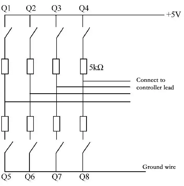
Figure 6: Identifying Controller Wire Functions
Table 3: Switch Method Wire Identification Table
| | No. | Q1 | Q2 | Q3 | Q4 | Q5 | Q6 | Q7 | Q8 |
| Rotation Judgment Method | 1 | ⬤ | ⬤ | ⬤ | ⬤ | ⬤ | ⚪ | ⚪ | ⚪ |
| 2 | ⬤ | ⬤ | ⬤ | ⬤ | ⚪ | ⬤ | ⬤ | ⚪ | |
| 3 | ⬤ | ⬤ | ⬤ | ⬤ | ⚪ | ⚪ | ⚪ | ⚪ | |
| 4 | ⬤ | ⬤ | ⬤ | ⬤ | ⚪ | ⚪ | ⚪ | ⚪ | |
| 5 | ⬤ | ⚪ | ⚪ | ⚪ | ⬤ | ⬤ | ⬤ | ⬤ | |
| 6 | ⚪ | ⬤ | ⚪ | ⚪ | ⬤ | ⬤ | ⬤ | ⬤ | |
| 7 | ⚪ | ⚪ | ⬤ | ⚪ | ⬤ | ⬤ | ⬤ | ⬤ | |
| 8 | ⚪ | ⚪ | ⚪ | ⬤ | ⬤ | ⬤ | ⬤ | ⬤ | |
| High-Voltage Brake Lever | 9 | ⬤ | ⬤ | ⬤ | ⬤ | ⚪ | ⚪ | ⚪ | ⬤ |
| 10 | ⬤ | ⬤ | ⚪ | ⬤ | ⚪ | ⚪ | ⚪ | ⬤ | |
| 11 | ⬤ | ⬤ | ⬤ | ⬤ | ⚪ | ⚪ | ⚪ | ⬤ | |
| 12 | ⬤ | ⬤ | ⚪ | ⬤ | ⚪ | ⚪ | ⚪ | ⬤ | |
| 13 | ⚪ | ⬤ | ⬤ | ⬤ | ⚪ | ⚪ | ⚪ | ⬤ | |
| 14 | ⚪ | ⬤ | ⚪ | ⬤ | ⚪ | ⚪ | ⚪ | ⬤ | |
| 15 | ⚪ | ⚪ | ⬤ | ⬤ | ⚪ | ⚪ | ⚪ | ⬤ | |
| 16 | ⚪ | ⚪ | ⚪ | ⬤ | ⚪ | ⚪ | ⚪ | ⬤ | |
| Low-potential brake lever | 17 | ⚪ | ⚪ | ⚪ | ⬤ | ⬤ | ⬤ | ⬤ | ⬤ |
| 18 | ⚪ | ⚪ | ⚪ | ⬤ | ⬤ | ⬤ | ⚪ | ⬤ | |
| 19 | ⚪ | ⚪ | ⚪ | ⬤ | ⬤ | ⚪ | ⬤ | ⬤ | |
| 20 | ⚪ | ⚪ | ⚪ | ⬤ | ⬤ | ⚪ | ⚪ | ⬤ | |
| 21 | ⚪ | ⚪ | ⚪ | ⬤ | ⚪ | ⬤ | ⬤ | ⬤ | |
| 22 | ⚪ | ⚪ | ⚪ | ⬤ | ⚪ | ⬤ | ⚪ | ⬤ | |
| 23 | ⚪ | ⚪ | ⚪ | ⬤ | ⚪ | ⚪ | ⬤ | ⬤ | |
| 24 | ⚪ | ⚪ | ⚪ | ⬤ | ⚪ | ⚪ | ⚪ | ⬤ |
Note: ● indicates the switch is closed; ○ indicates the switch is open.
Assuming the circuit between Q4 and Q8 is the throttle signal lead, close Q4 and Q8 to begin identifying the throttle signal leads. If the motor stops rotating when a particular switch is opened or closed, that indicates the lead is part of the throttle signal circuit. There may be one or two throttle signal leads. Some leads, whose voltage levels have no bearing on the motor’s rotation, can be left unconnected in emergency situations.
(2) Connecting a Brushless Controller to a Brushless Motor Most brushless motors are connected to brushless controllers as follows:
A brushless motor typically has 8 wires connected to the controller; when wiring, follow the color-coded correspondence. The 3 thick wires are the stator leads, and the other 5 thin wires are the motor’s Hall effect sensor wires. Generally, the thick blue wire is motor phase A, the thick green wire is motor B phase, and the yellow thick wire represents the motor’s C phase. The red thin wire is the 5V positive power supply, the black thin wire is ground, the blue thin wire is position sensor phase A, the green thin wire is position sensor phase B, and the yellow thin wire is position sensor phase C. Brushless controllers and brushless motors come in two phase-angle configurations: 60° and 120°. Care must be taken to ensure proper correspondence when wiring; otherwise, the motor will not rotate normally.
Common brushless motor driver chips include the MC33035 and MC33033. For the MC33035 chip, if pin 22 is grounded, it is used to drive a 120° brushless motor. Brushless motor: If pin 22 is left floating or connected to a high voltage, it is used to drive a 60° brushless motor. For the MC33033, if pin 18 is grounded, it is used to drive a 120° brushless motor; if pin 18 is left floating or connected to a high voltage, it is used to drive a 60° brushless motor.
If the brushless motor rotates in the opposite direction, the phase angles of the brushless controller and the brushless motor do not match; adjust the motor’s rotation direction. To do this, swap the A and C Hall sensor wires connecting the brushless motor to the brushless controller; simultaneously, swap the main phase wires A and B connecting the brushless motor to the brushless controller.
(3) How to Replace Circuit Components: If an integrated circuit or MOSFET is found to be damaged, it should be replaced.
a. Remove the integrated circuit. To remove it, use the outer flame of an alcohol lamp to heat the solder pads on the printed circuit board where the integrated circuit is attached. Move the printed circuit board quickly and evenly until the solder on all pads has melted, then use tweezers to remove the integrated circuit from the printed circuit board. When soldering, thoroughly clean the solder from the vias, properly position the integrated circuit, and quickly solder each pin using a soldering iron with a good ground connection. Be sure to work quickly to avoid excessive local temperatures caused by prolonged soldering, which could damage the circuit or pads.
b. Remove power devices. During removal, cut off the leads of the MOSFET or three-terminal voltage regulator IC, then desolder their leads one by one. Take care to avoid damaging the PCB pads when removing components with large leads.
c. Soldering integrated circuits and power devices. After removing the integrated circuits and power devices, clean the pads and remove any excess solder, exposing the pad holes. After inserting the integrated circuits and power devices into their respective positions, use a soldering iron rated at 30 W or less to solder the component leads to the corresponding pads. Solder each connection in a single pass; do not hold the soldering iron on any single lead for too long, to avoid damaging the component’s internal circuitry.
(4) When installing the controller, ensure that the connectors linked to the controller are positioned perpendicular to the ground to prevent water from accumulating in the connectors. Secure the controller’s leads to the vehicle frame with nylon cable ties to prevent damage caused by friction between the leads and the frame. Install the controller as high as possible above the ground, and position the opening of the controller housing facing downward to prevent water from entering and damaging the controller.
Case 13: Brushed Motor Still Does Not Run After Replacing a Damaged Controller
Fault Symptoms:
After replacing a damaged controller on a brushed motor, the motor still fails to run.
Troubleshooting:
After replacing a damaged controller on a brushed motor, the motor still fails to run. First, inspect all controller wiring; but no abnormalities were found. Next, the controller was connected only to the throttle power supply, yet the motor still showed no response. Upon testing the voltage on the controller’s positive power supply wire, no voltage was detected, although the instrument panel indicated power was present.
Upon inspecting the wiring between the power lock switch and the controller, an open circuit was discovered. After reconnecting the power lock switch to the controller’s positive power supply wire and testing the vehicle, the fault was resolved.
The root cause was that the controller’s positive power supply wire serves as a switch that controls the internal power supply of the controller; this wire connects the power lock switch to the positive terminal of the battery. The controller’s internal power supply can only function normally when the voltage on this wire matches the voltage at the positive terminal. The open circuit in the positive wire caused the aforementioned malfunction.
Case 14: Brushless Motor Rotates but Lacks Power and Produces Loud Noise
Fault Symptoms:
The brushless motor can rotate but lacks power and produces loud noise.
Troubleshooting:
Since this vehicle uses the original factory controller, there is no issue with wiring compatibility. Testing with a brushless controller tester revealed that one phase was missing from the controller’s output. After replacing the controller, the motor operated normally.
The root cause is that since a brushless motor has a three-phase winding, if one phase is open-circuited, the motor can still rotate but will run weakly and produce excessive noise.
Additionally, misalignment between the motor and controller phase lines can also cause a phase break in the motor.
Case 15: Brushless Motor Does Not Turn Despite Normal Power, Lights, and Horn
Fault Symptoms:
The brushless motor does not turn, although the lights and horn are working normally.
Troubleshooting:
First, disconnect the throttle cable and reconnect a new one, but the fault persists, suggesting a controller malfunction. Using a multimeter to test the controller’s power terminals and the motor’s Hall effect sensors revealed no voltage at all.
Testing the Hall effect sensor’s power line also showed no voltage, indicating the controller is damaged. After replacing the controller with a new one and testing the vehicle, the fault was resolved.
The root cause is that without power to the Hall effect sensor, it cannot send a signal to the controller; without a signal, the controller cannot supply power, causing the motor to stop rotating.
Case 16: Controller Cannot Detect Signal from the Assist Sensor
Fault Symptoms:
The controller cannot detect the signal from the assist sensor.
Troubleshooting:
The function of the electric bicycle’s assist sensor is to detect pedal torque or pedal speed signals when the electric bicycle is in assist mode. Based on the magnitude of the signal from the assist sensor, the controller adjusts the motor’s electrical drive power output, achieving automatic coordination between human power and electric power to jointly drive the electric bicycle.
The Hall effect sensor is mounted on a bracket next to the bottom bracket, which is fitted with a magnetic ring. As the bottom bracket rotates one full revolution, the five magnets on the magnetic ring cause the Hall effect sensor to output five pulses. When the controller detects this signal, it calculates the required assist torque and adjusts the motor’s supply voltage accordingly. Newer assist sensors can also detect the direction of rotation of the bottom bracket, supplying power to the motor only when it is rotating forward.
If a fault occurs where the controller cannot detect the assist sensor signal, follow these troubleshooting steps:
① Check whether the distance between the assist sensor and the magnet is between 2 and 5 mm. If the distance is too great, no signal will be output; adjust the distance until it is appropriate.
② If there is still no signal output after adjustment, check the assist sensor’s output signal wire. If they are normal, check whether the assist sensor has a 5V voltage. If there is no 5V voltage, this indicates a fault in the controller’s internal power supply; handle this as if the controller has no operating power. If the 5V voltage is normal, test the Hall effect sensor.
Case 17: Assist Sensor Provides Assistance Only When Rotating in Reverse
Fault Symptoms:
The electric bicycle’s assist sensor provides assistance only when rotating in reverse; it does not function when rotating forward.
Troubleshooting:
A fault has occurred where the electric bicycle’s power-assist sensor provides assistance only when reversing and does not function when moving forward. The primary cause of this fault is that the magnetic ring corresponding to the sensor was installed in the wrong orientation. Simply install the magnetic ring with the arrow pointing in the direction of the bike’s travel.
Both the sensor and the magnetic ring should be installed on the right side of the bike. If, due to the bike’s design, a manufacturer has installed them on the left side, the magnetic ring should also be installed in the opposite direction. Currently, some electric bicycle controllers use AS-type sensors, which feature forward/reverse rotation detection; they supply power to the motor only when rotating forward to prevent safety hazards caused by reverse assistance.
Case 18: Controller Does Not Operate When the Speed Control Signal Is 5V
Fault Symptoms:
The controller does not operate when the speed control signal is 5V.
Troubleshooting:
The controller does not operate when the electric bicycle’s speed control signal is 5V. This is a protective feature built into smart electric bicycle controllers, designed to prevent the bike from running out of control in the event of a damaged throttle. The voltage from a normal electric bicycle throttle cannot reach 4.8V. When the voltage exceeds 4.8V, the controller interprets this as a throttle malfunction and cuts off power to the motor. Therefore, when the electric bicycle’s speed control signal is 5V, the controller will not operate; this is normal behavior.
Case 19: No Response After the Power Lock Is Engaged
Fault Symptoms:
The electric bicycle shows no response after the power lock is engaged.
Troubleshooting:
Analysis of the fault symptoms indicates an abnormality in the power supply system. The circuit is shown in Figure 7.
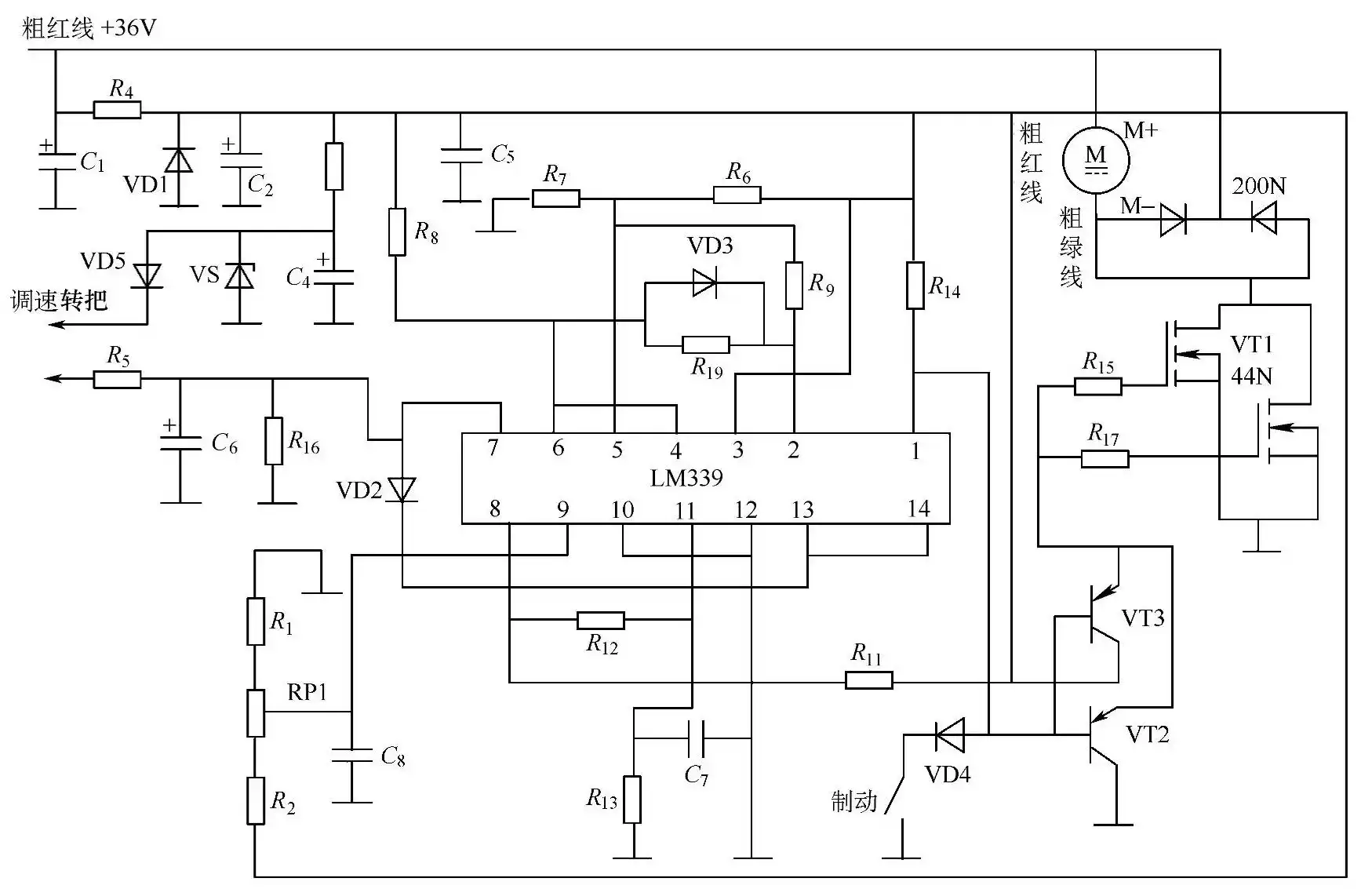
Figure 7: Xinchenzhiguang electric bicycle controller circuit
Upon inspection, the fuse was found to have blown; it is suspected that an abnormal load caused it to fail due to overcurrent. When the digital multimeter was set to the diode range to measure the load’s resistance to ground, the multimeter’s buzzer sounded, indicating that the load was indeed shorted. After disconnecting the controller’s 36V power supply line, the multimeter no longer beeped, and the resistance returned to normal, indicating that the fault was located in the controller. Internal components in the controller that cause a short circuit between the 36V power supply and ground are most often due to damage to field-effect transistor (FET) power amplifiers. Upon inspecting the field-effect transistors, one was found to be shorted. The fault was resolved after replacing the field-effect transistor and the fuse.
Case 20: Power Indicator Lights Up, but the Bike Cannot Be Ridden
Fault Symptoms:
After turning on the power lock of an electric bicycle, the power indicator lights up, but the bike cannot be ridden.
Troubleshooting:
Analysis of the fault symptoms indicates that the motor, controller, or the braking and speed control circuits are malfunctioning. The circuit is shown in Figure 7.
Measurements showed no motor drive voltage output from the controller, indicating that the fault was caused by a malfunction in the controller or related components. Inspection of the control signals output by the brake lever and throttle lever confirmed they were normal, indicating the fault lies within the controller. Measurement showed normal power supply at pin 3 of the LM339, and the presence of excitation pulses at pin 10 of the LM339, indicating the fault is located in the signal amplification section. An in-circuit inspection revealed that the collector-emitter junction of the excitation transistor VT2 was shorted due to breakdown. After replacement, the fault was resolved.
Case 21: WMB-Type Controller with No Drive Pulse Output
Fault Symptoms:
The WMB-type controller has no drive pulse output.
Troubleshooting:
Analysis of the fault symptoms indicates that the controller, brake lever, or throttle lever is malfunctioning.
Measurements showed no motor drive voltage output from the controller, indicating that the fault was caused by an abnormality in the controller or related components. Checking confirmed that the control signals from the brake lever and throttle lever were normal, confirming that the fault originated in the controller. Measurements showed that the power supply at pin 3 of the LM339 was normal, but there was no excitation pulse output at pin 10 and no sawtooth pulse at pin 6 of the LM339, indicating that the fault occurred in the sawtooth pulse generation circuit. Upon inspecting the external components connected to pin 6 of the LM339, it was found that C8 was leaking current; the fault was resolved after replacement.
Case 22: WMB-Type Controller Has No Drive Pulse Output
Fault Symptoms:
The WMB-type controller has no drive pulse output.
Troubleshooting:
Analysis of the fault symptoms indicates that the controller, brake lever, or throttle handle is faulty.
Measurements showed no motor drive voltage output from the controller, indicating the fault was caused by a malfunction in the controller or related components. Upon inspecting the control signals output by the brake lever and throttle handle, it was found that the brake lever signal remained at a low level at all times, indicating a fault in the brake lever or its wiring. Inspection confirmed a fault in the brake lever; the issue was resolved after replacement.
Case 23: Narrow Speed Control Range of WMB-Type Controller
Fault Symptoms:
The WMB-type controller has a narrow speed control range.
Troubleshooting:
Analysis of the fault symptoms indicates that the controller or the throttle grip is faulty.
When rotating the throttle grip, the speed control pulses measured at pin 9 of the LM339 were abnormal, indicating a fault in the speed control circuit. When rotating the throttle grip, the voltage measured at pin 3 of the Hall IC was abnormal, while the power supply at pin 1 was normal, indicating a fault in the Hall IC or the permanent magnet strip. After replacing the Hall IC, the fault was resolved.
Case 24: Controller Composed of a PCI6C58B and an LM393 Fails to Output Excitation Pulses
Fault Symptoms:
The controller does not output excitation pulses.
Troubleshooting:
Based on an analysis of the fault symptoms, it can be preliminarily determined that the fault lies in the motor, controller, or the braking and speed control circuits. The circuit is shown in Figure 8.
Measurements show that the controller does not output a motor drive voltage, indicating a malfunction in the controller and its control system. Inspection revealed that the control signals output by both the brake lever and the throttle lever were abnormal; since it is unlikely that both the brake lever and the throttle lever would fail simultaneously, a power supply issue was suspected. Measurement of their power supply voltage revealed a reading of less than 1 V, whereas the normal voltage is 5 V. Since the 5 V voltage is supplied by the controller, this indicates that the 5 V voltage regulator circuit inside the controller is malfunctioning.
The 5 V voltage regulator circuit of this controller consists of R12 and TR3. Upon inspection, R12 and TR3 were found to be normal, so we suspected that the filter capacitors C5, C6, and others were faulty. After desoldering C5 for inspection, we found it was leaking current. We replaced C5 with a 100μF/25V capacitor, and the 5V voltage returned to normal. After reconnecting the controller to the throttle, brake lever, and motor, the fault was resolved.
Case 25: Controller Built with a PCI6C58B and an LM393 Shows No Drive Pulses
Fault Symptoms:
The controller shows no drive pulses.
Troubleshooting:
Refer to Figure 8 for the circuit diagram. Following the troubleshooting approach from the previous example, the control signals output from the brake lever and throttle lever were found to be normal, indicating that the fault lies within the controller. After disassembling the controller, no drive pulses were detected at pin 7 of the LM393. Subsequently, no excitation pulse input at pin 5, indicating that the PCI6C58B microcontroller was not outputting excitation pulses. For the PCI6C58B to function properly, it requires not only a 5V power supply but also a reset signal and a clock signal. When measuring pins 17 and 18 of the PCI6C58B, no clock signal was detected, indicating that the fault was due to an abnormality in the clock oscillator circuit. C12 and C13 were found to be normal. After replacing the crystal oscillator, the fault was resolved.
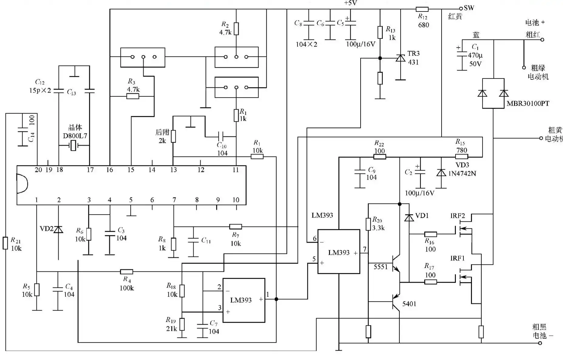
Figure 8: Controller Circuit Composed of PC16C58B and LM393
Case 26: Controller Composed of PC16C58B and LM393 Fails to Generate Excitation Pulses
Fault Symptoms:
The controller does not generate excitation pulses.
Troubleshooting:
Following the troubleshooting approach from the previous example, the control signals output from the brake lever and throttle were found to be normal, indicating that the fault occurred inside the controller. After disassembling the controller, pin 7 of the LM393 was found to have a drive pulse output, while pin 5 had a pulse input, indicating that the fault occurred in the signal amplification section. Upon inspecting the signal amplification section, it was discovered that there was no supply voltage; this voltage is generated by the voltage regulator circuit consisting of R15 and VD3. Inspection revealed that VD3 was shorted; after replacing it, the fault was resolved.
Case 27: Controller Composed of a PCI6C58B and an LM393 Outputs Normally with a Fully Charged Battery but Fails After Some Use
Fault Symptoms:
The controller produces normal output pulses with a fully charged battery, but fails to output a drive voltage after the battery has been in use for some time.
Troubleshooting:
Analysis of the fault symptoms suggests either a decrease in battery capacity or a false trip of the undervoltage protection circuit inside the controller. Using a DC regulated power supply as a test controller, it was observed that when adjusting the power supply’s output voltage, the controller ceased to output drive pulses even before the voltage dropped to the undervoltage protection threshold, indicating that the fault lies within the controller.
Refer to Figure 8. This controller employs two sets of undervoltage protection circuits: one consists of an LM393, R18, and R19; the other consists of the PCI6C58B’s sense resistor. Inspection revealed that the resistance of R18 had increased; the fault was resolved after replacing the resistor.
Case 28: Controller Composed of an 89C2051, IR2103, and D4324 Fails to Output Excitation Pulses
Fault Symptoms:
The controller does not output excitation pulses.
Troubleshooting:
Based on an analysis of the fault symptoms, the issue was suspected to stem from abnormalities in the motor, the controller, or the braking and speed control circuits. Refer to Figure 9 for the circuit diagram.
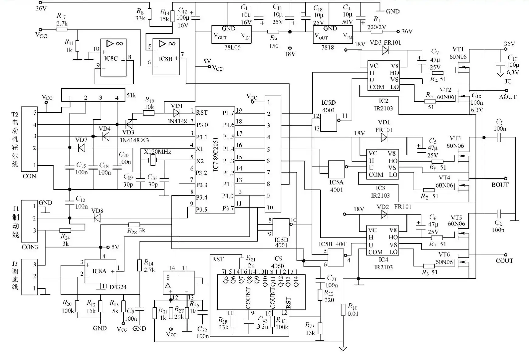
Figure 9: Controller circuit composed of 89C2051, IR2103, and D4324
Measurements showed that the controller was not outputting any motor drive voltage, indicating a malfunction in the controller and its control system. Inspection revealed that the control signals from both the brake lever and throttle were abnormal; when the power supply to these components was measured, the voltage was found to be 0 V, whereas the normal voltage should be 5 V. Since the 5 V voltage is supplied by the controller, this indicates that the 5 V voltage regulator circuit inside the controller is malfunctioning.
This controller employs two sets of voltage regulator circuits: one for 18 V and one for 5 V. First, a three-terminal regulator 7818 and R1 convert the 36V voltage from the battery box to 18V; then the three-terminal regulator 78L05 generates a 5V voltage. A measurement across the filter capacitor C1 showed a voltage of 18V, but no 5V voltage was present across C12. The voltage across C11 was normal, indicating a fault in the 78L05 or its load. After disconnecting its load, the voltage across C12 remained unchanged, confirming that the 78L05 was damaged. The fault was resolved after replacing it.
Case 29: Controller Composed of an 89C2051, IR2103, and D4324 Fails to Output Excitation Pulses
Fault Symptoms:
The controller does not output excitation pulses.
Troubleshooting:
Analysis of the fault symptoms suggests a fault in the motor, the controller, or the braking and speed control circuits.
Measurements showed no drive voltage input to the motor’s three-phase windings, indicating a fault in the controller and its control system. Inspection revealed that the control signals output by the brake lever and throttle were normal, confirming a controller malfunction.
Refer to Figure 9: To provide drive signals to the brushless motor, it employs three drive circuits. Since it is unlikely that all three amplifiers failed simultaneously, the fault lies in the pulse-width modulation (PWM) circuit. Because the 89C2051 is a microcontroller, its normal operation requires not only a stable 5V power supply but also proper reset and clock signals. A measurement at pin 20 of the 89C2051 (not shown in the figure) revealed a 5V voltage, while pin 1 did not receive a reset signal (transitioning from high to low) at power-on. This indicates a fault in the reset circuit. Upon inspecting the reset circuit, it was found that capacitor C12 was open-circuited; the fault was resolved after replacing it.
Case 30: Controller Composed of the 89C2051, IR2103, and D4324 Has a Channel with No Excitation Pulse Output
Fault Symptoms:
One channel of the controller has no excitation pulse output.
Troubleshooting:
Analysis of the fault symptoms indicates a fault in the motor, controller, braking system, or speed control circuits.
Referring to Figure 9, measurements showed no drive voltage input to the motor’s three-phase windings, indicating a malfunction in the drive circuit or the 89C2051. Testing revealed that amplifier IC2 (IR2103) received a signal input but produced no output, indicating that the amplifier was not functioning properly. Since its power supply and external components were found to be normal, IC2 was determined to be faulty; the fault was resolved after replacing it.
Case 31: Controller Composed of a PIC58, MC34063A, and CD4069 Is Not Outputting Excitation Pulses
Fault Symptoms:
The controller is not outputting excitation pulses.
Troubleshooting:
Based on the failure symptoms, the motor, controller, or the braking and speed control circuits were suspected to be malfunctioning.
Measurements showed no motor drive voltage output from the controller, indicating a malfunction in the controller and its control system. Inspection revealed that the control signals from both the brake lever and the throttle were abnormal, and upon measuring their power supply, the voltage was found to be 0 V, indicating a fault in the 5.5 V power supply within the controller.
First, check for blown or discolored components. To convert the 36 V voltage to 5.5 V, this controller employs a DC-DC switch-mode power supply consisting of the MC34063A thick-film IC, the storage inductor L1, and the freewheeling diode VD17. Measurements showed normal supply voltage at pins 1 and 6–8 of the MC34063A, but no voltage output at pin 2, indicating a fault in the circuitry connected to or from pin 2 of the MC34063A. Since the external components were found to be normal, the fault was determined to lie with the MC34063A itself; replacing it resolved the issue.
Case 32: Controller Composed of an LM339 and an NE555 Fails to Output Excitation Pulses
Fault Symptoms:
The controller does not output excitation pulses.
Troubleshooting:
Based on an analysis of the fault symptoms, the issue is suspected to be a malfunction in the motor, the controller, or a fault in the braking or speed control circuits.
Measurements showed that the controller was not outputting any motor drive voltage, indicating a fault in the controller and its control system. Inspection revealed that the control signals from both the brake lever and the throttle were abnormal; when the supply voltage to these components was measured, it was found to be 0 V, indicating a fault in the controller’s internal 5 V power supply.
Upon inspecting the internal components of the controller, it was discovered that fuse FU1 had blown and turned black, indicating a component inside the controller had caused a severe short circuit. Since the components responsible for blowing the fuse were primarily located in the power amplification section, an in-circuit inspection revealed that the field-effect transistor VT7 was shorted, while other components were normal. After replacing VT7 and FU1, the fault was resolved.
Case 33: Controller Built with an LM339 and NE555 Fails to Output Excitation Pulses
Fault Symptoms:
The controller does not output excitation pulses.
Troubleshooting:
Following the troubleshooting approach from the previous example, the control signals output by the throttle and twist grip were found to be normal. Measurement of pin 14 of the LM339 revealed no pulse-width modulation (PWM) output; subsequent measurement of pin 8 showed no sawtooth trigger pulse input, indicating a malfunction in the sawtooth pulse generation circuit. The sawtooth pulse generation circuit consists of the NE555 timing circuit and associated components. After verifying that the power supply to pins 4 and 8 of the NE555 was normal and that the external components were in good condition, the NE555 was suspected to be faulty. After replacement, pin 14 of the LM339 was able to output a pulse with adjustable width, and the fault was resolved.
Case 34: 36V Brushed Motor Runs Uncontrollably
Fault Symptoms:
When the bike frame is raised and the power switch is turned on, the motor spins at high speed; even when the brake lever is squeezed, the wheels continue to spin uncontrollably.
Troubleshooting:
First, turn off the power switch, then disconnect the speed control twist grip wire. If the motor continues to spin uncontrollably after turning the power switch back on, this indicates a controller malfunction. Remove and disassemble the controller; a multimeter inspection ultimately revealed that an internal MOSFET had shorted out. After replacing the MOSFET with one of the same model, the runaway phenomenon ceased.
Case 35: Brushed Motor Runs Uncontrollably
Fault Symptoms:
With the bike frame propped up, turn on the power switch; the motor spins at high speed. When the brake lever is squeezed, the wheels stop rotating.
Troubleshooting:
First, turn off the power switch, then disconnect the throttle control wire. Next, turn on the power switch; if the motor stops running, this indicates that the controller is functioning normally. Reconnect the throttle control wire and turn on the power switch, at which point the motor continues to run. Using a multimeter set to the 10V DC voltage range, with the black probe grounded and the red probe connected to the speed control grip wire, the following readings are obtained: the Hall voltage is 5V, the ground voltage is 0V, but the output voltage on the speed signal wire is 0V. This indicates a malfunction in the speed control grip controller. Replace the speed control grip with the original model to resolve the fault.
Case 36: Runaway Brushed Motor
Fault Symptoms:
Lift the bike frame, turn on the power switch, and the motor spins at high speed; when the brake lever is squeezed, the wheel stops rotating.
Troubleshooting:
Turn off the power switch, then disconnect the throttle control wire. Turn the power switch back on; if the motor stops running, this indicates that the controller is functioning normally. Reconnect the throttle control wire and turn on the power switch; if the motor continues to run uncontrollably, this indicates an open circuit in the throttle controller or its control wire, or a poor connection at the connector. After inspecting the control wire and finding no breaks, and verifying that the throttle controller is functioning normally, short-circuit the Hall sensor wires (output and input), the speed control wire, and the ground wire at the connector one by one. When the ground wire is shorted, the motor stops running. Upon disassembling the connector, severe internal corrosion was discovered. After replacing the part, the fault disappeared.
Case 37: Brushed Motor Fails to Operate When Powered On
Fault Symptoms:
When the power switch is turned on and the throttle is turned, the motor does not rotate, but the battery reads normal.
Troubleshooting:
Remove the controller and use a controller fault tester to verify that all readings are normal. After reinstalling the controller in its original position and reconnecting the wires, unplug the brake switch connector, turn on the power switch, and accelerate; if the motor runs normally, this indicates that the throttle is functioning properly. If the fault persists after engaging the brake switch, this indicates a fault in the brake switch. Unplug the brake switch connector; upon inspection, the switch was found to be shorted. After replacing it with a new brake switch, the fault disappeared.
Case 38: Brushed Motor Does Not Operate When Powered On
Fault Symptoms:
When the power switch is turned on and the throttle is gripped, the rear wheel does not rotate, but the battery charge indicator shows a full charge.
Troubleshooting:
When the power switch is turned on and the battery charge level appears sufficient, the rear wheel does not rotate when the throttle is turned; the needle on the battery charge gauge immediately drops.
The causes of this fault are as follows:
a. Insufficient battery capacity.
b. Excessive contact resistance somewhere in the circuit, commonly occurring at wire splices, connectors, etc.
Replacing the battery with a fully charged one of the same model did not resolve the issue. Upon removing the busbar box, corrosion was found on the main wire connector. After sanding it with fine sandpaper and reassembling, the fault was resolved.
Case 39: Brushed Motor Lacks Power
Fault Symptoms:
The electric bicycle maintains normal speed under no-load conditions but lacks power when riding.
Troubleshooting:
Prop up the frame, accelerate normally by turning the throttle grip, but the bike cannot move forward. The controller housing felt only slightly warm to the touch, leading to the conclusion that the internal current-limiting function was malfunctioning. The purpose of current limiting is to activate when the current reaches a certain value, restricting the current within a specific range, thereby providing multiple protective functions for the motor, battery, and the controller itself. After disassembling the controller and testing the current-limiting circuit, a cold solder joint was found in the current-limiting resistor. After resoldering and reassembling the unit, the fault was resolved.
Case 40: Brushed Motor Does Not Operate
Fault Symptoms:
Prop up the frame and turn on the power switch, but the rear wheel does not rotate.
Troubleshooting:
Using a multimeter set to the 20V DC range, measure the high and low voltages of the brake lever’s output signal. If the voltage on the brake lever signal wire changes by more than 4V when the brake lever is squeezed, this indicates that the brake lever is functioning normally. Then, remove the controller and inspect the resistors, capacitors, diodes, and other components surrounding the main chip; no abnormalities were found. The fault disappeared after replacing the main chip with a new one.